How Do I: Build a Bench Power Supply from a PSU!
Here’s a fun build on how to build a Bench Power Supply, which I use for testing flashlights, among other things. Read on for info and videos!
I teased a working unit of a bench power that I built last year. I’d always intended to build a second unit for a friend, and I finally did that. I cataloged the process in the best way I could figure out, and here’s that post! So here’s my latest (and only second) “How Do I…” Build a Bench Power from a PSU. This isn’t a review, it’s just how I built this thing. And I’m not an electrical engineer or have any background in engineering or electronics. Everything I learned and used in this post, I read from internet sources. They probably know more and could help you more than I can. But I’m happy to pass this knowledge along, and I hope you find it useful.
Furthermore, there are many other ways to build this unit, and most of them are easier than this way. I chose this way specifically because I wanted to have a bench power that wasn’t much (if any) larger than the computer PSU that I was using. At the end, how you build it will be up to your needs.
And finally, let’s get this out of the way: This won’t be the cheapest way to obtain a bench power supply. I started off thinking the cost would probably be along the lines of a similar unit, but at this point, I can’t really say that it is. What I can say is that I learned grossly more doing this than I would have if I’d just bought a unit, and that knowledge is worth vastly more than the difference in cost.
Disclaimer:
- I am not an electrical engineer.
- You should assume that all of the parts used in this build intend to kill you, and treat them with respect.
- Treat this as a learning experience – there are other off-the-shelf bench powers that are as (or more) capable, and likely less costly.
- Build this at your own risk!
Price and Parts List
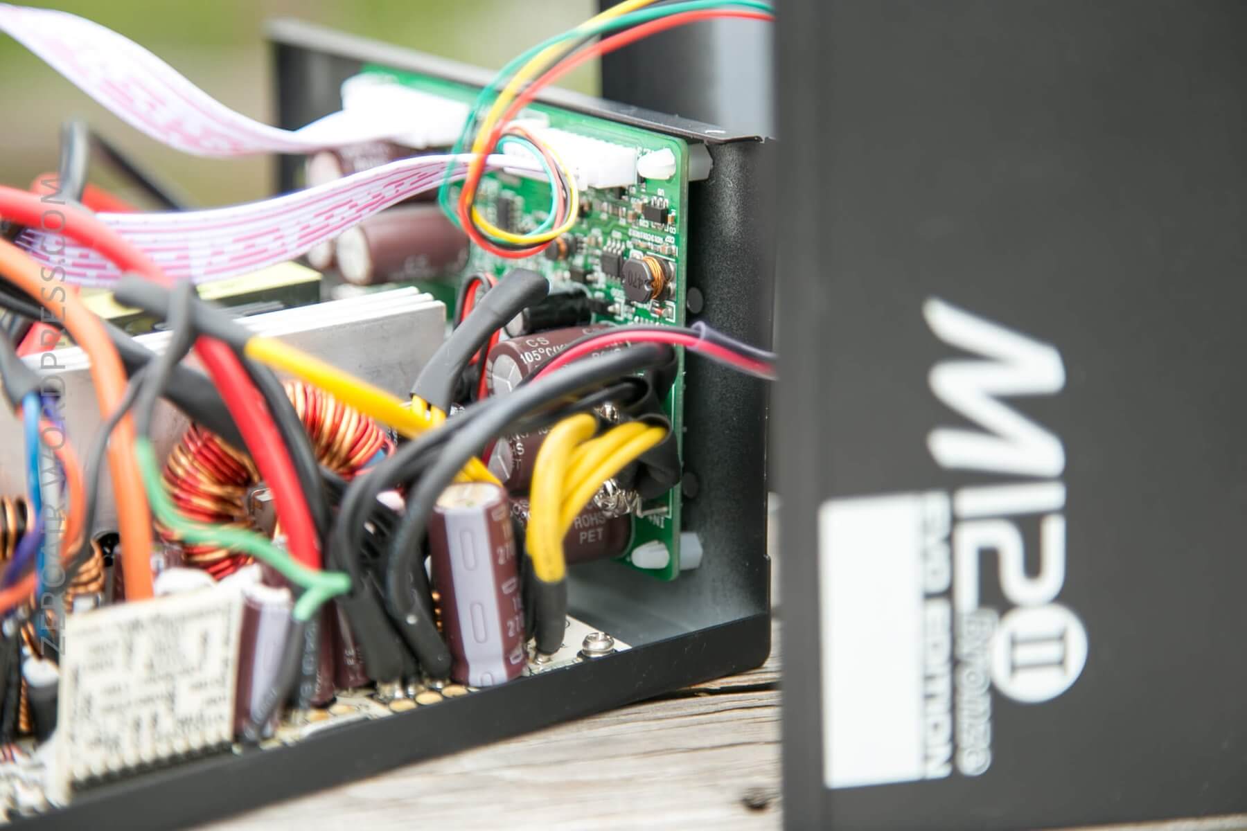
- $22.72 ATX Power supply. I used this Seasonic M12II-620 full modular unit.
- $48.99 RuiDeng Constant Voltage Current Converter. I used the RuiDeng DPS5020.
- $1.75 (5) Binding posts. I use these.
- $3.55 DANIU Electrical Cutting Plier Wire Cable Cutter Side Snips Flush Pliers Tool. (Yes, I’m putting these in the “must-have” category).
- $8.94 Excellway TC19 330Pcs Wire Crimp Terminals Assorted Kit
Total of the above: $85.95. You can already see that an off-the-shelf unit will be less expensive. There’s a chance you’ll have some of this in your electronics drawer, but you’ll certainly have to buy at least some of the parts. You may read on to understand my decisions to continue the project, even at this cost.
Things that are nice to have for this build:
- $4.66 (1m) 12 Gauge Silicone-coated wire. I used this. 14 Gauge would probably be ok; that’s really up to you.
- $4.99 4mm Gold Bullet Connector Banana Plug. You’ll want at least a few of this type, but there are tons of other options.
- $3.30 (50) P100-B1 Dia 1.36mm 180g Spring Test Probe Pogo Pin
- $2.88 DANIU 12Pcs Red Black Insulation Boot Metal Alligator Clips
- $2.39 100Pcs M3 Brass Hex Screw Bolt Nut 3mm Diameter 1.5mm Thread Height
- $1.59 Suleve™ M3BN1 M3*4mm H62 Brass Knurl Nuts DIY Accessories 100pcs
- $5.99 Suleve™ M3SS1 M3 Stainless Hex Socket Button Head Screws Allen bolt Nut Assortment Kit 340pcs
There’s a strong chance you’ll find yourself in need of something more than the above, but this list should cover most of what you need.
Quick Thoughts
I could not be happier to have a bench power. I’ve found it ridiculously useful in my flashlight testing, and just with stuff around the house.
Second to that, I learned so much when researching this (and building two), and that’s been worth at least the cost, and realistically much more.
The downside of this particular build is that my max voltage available is around 11V. For most of the flashlight stuff I do, this is fine (though there are some 12V emitters becoming more common now). Ideally, a supply for flashlight needs would be a minimum of 15V (and the next step past 12V input is probably 24V input). 24V input would be perfect. Maxing out the RuiDeng unit would be even better, I suppose….
Not So Quick Thoughts
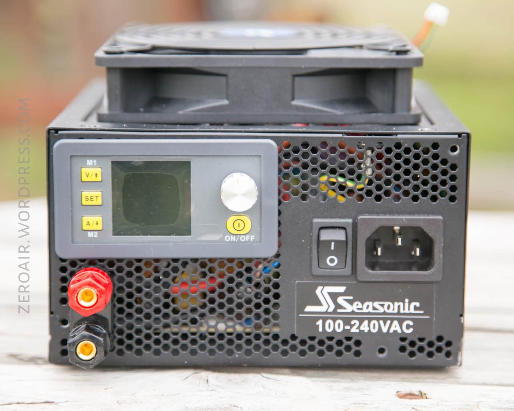
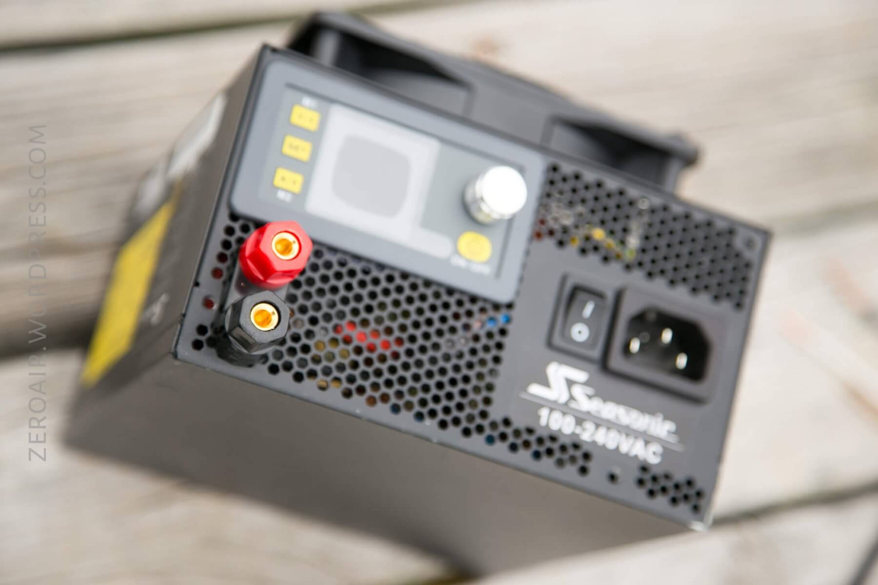
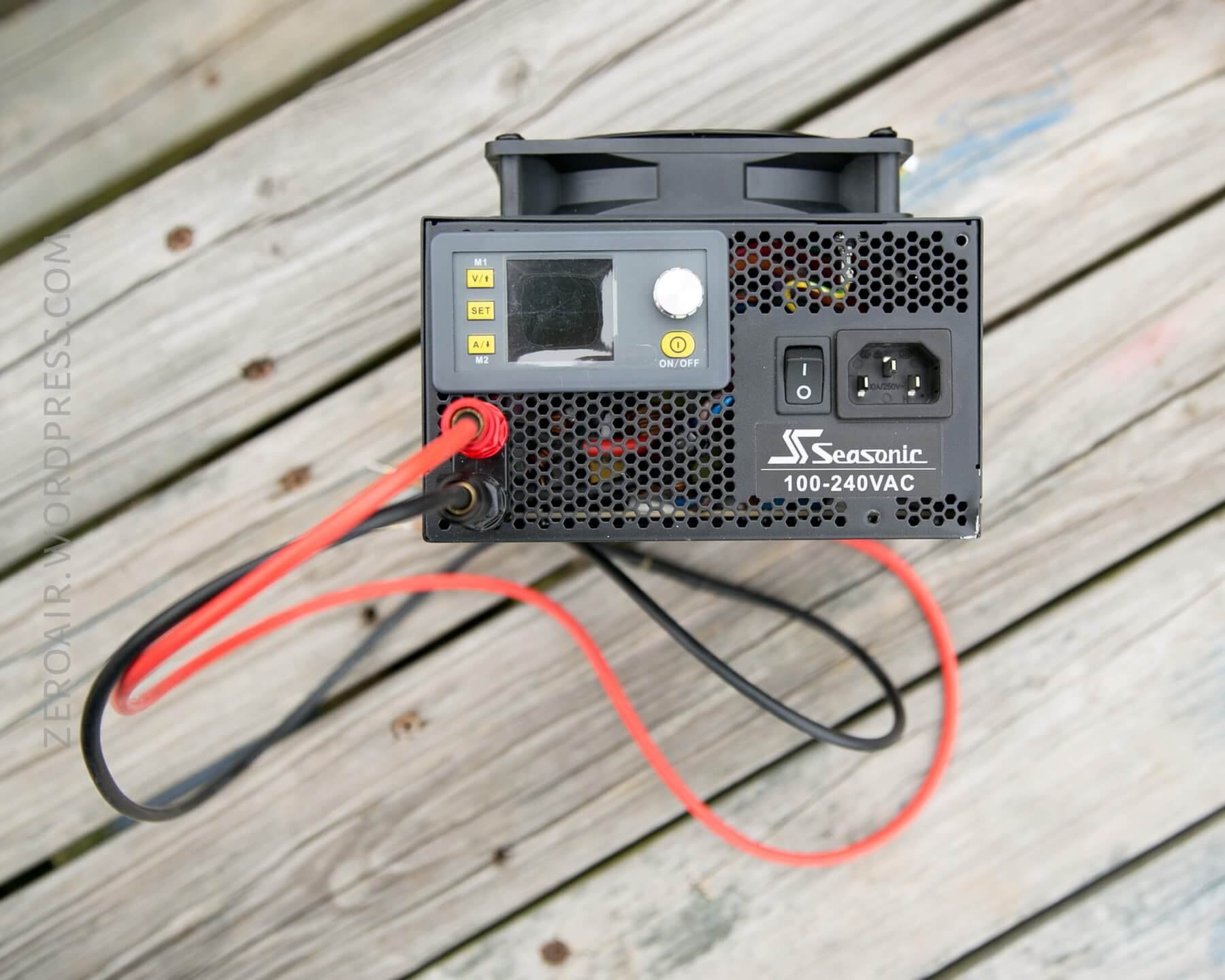
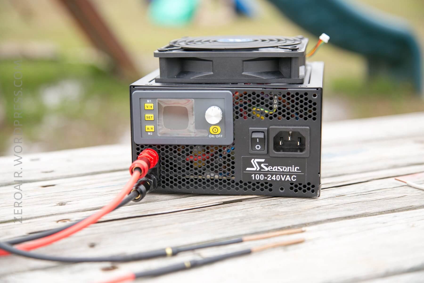
Overview
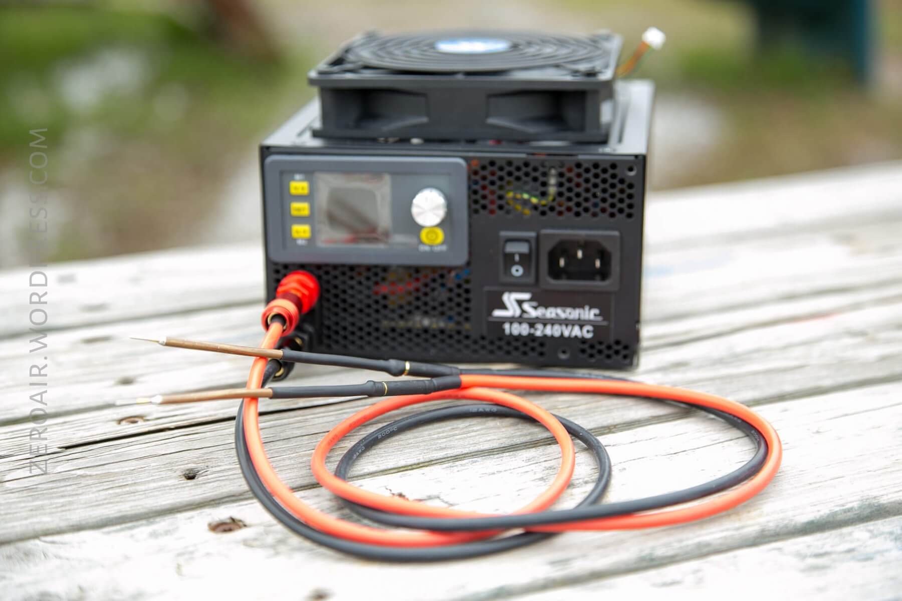
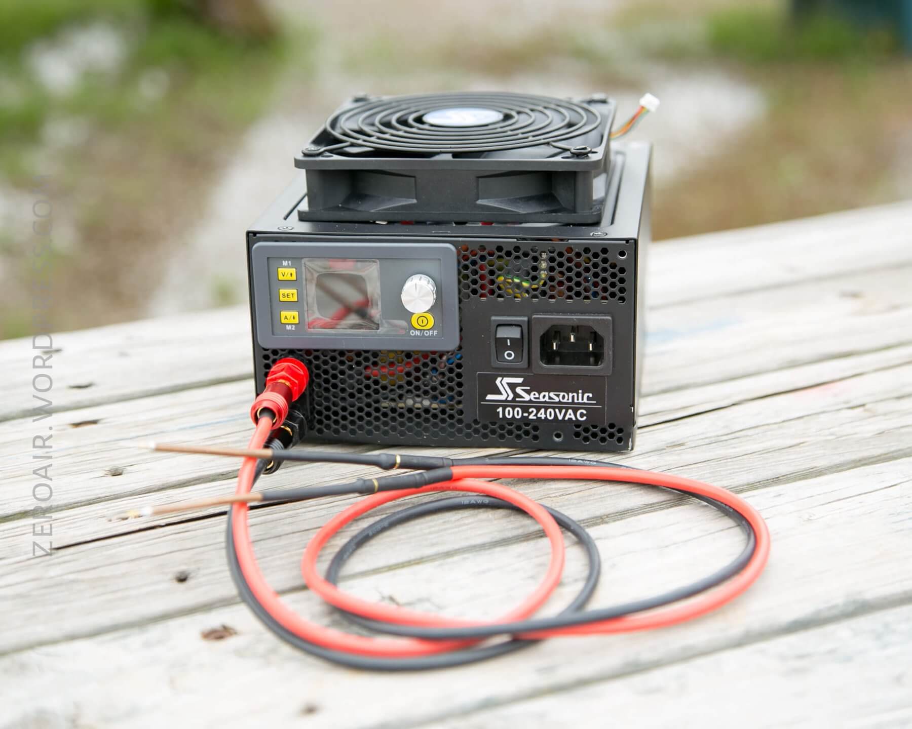
Here’s basically what we’re building. It’s an ATX computer power supply, to which I’ve added a set of banana plugs attached to a RuiDeng 5020 adjustable current and voltage power supply.
And this is useful in a ton of ways. I connect leads to the red and black banana jack at the bottom left there, and I can supply anything with up to ~11V at ~20A or so. And any variation below those numbers.
Size
I should say up front that there was a strict size limit for this process. My goal (and likely your only reason to follow this log) was to fit the whole of the additional parts inside a typical/standard ATX Power Supply. In the end (both builds!), this didn’t quite work out, but I do believe it could actually be done. It’d just require more modification than I was willing to perform (for now! I might still have another build with that goal.)
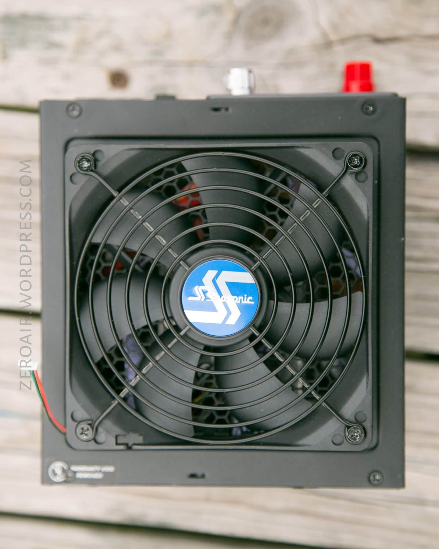
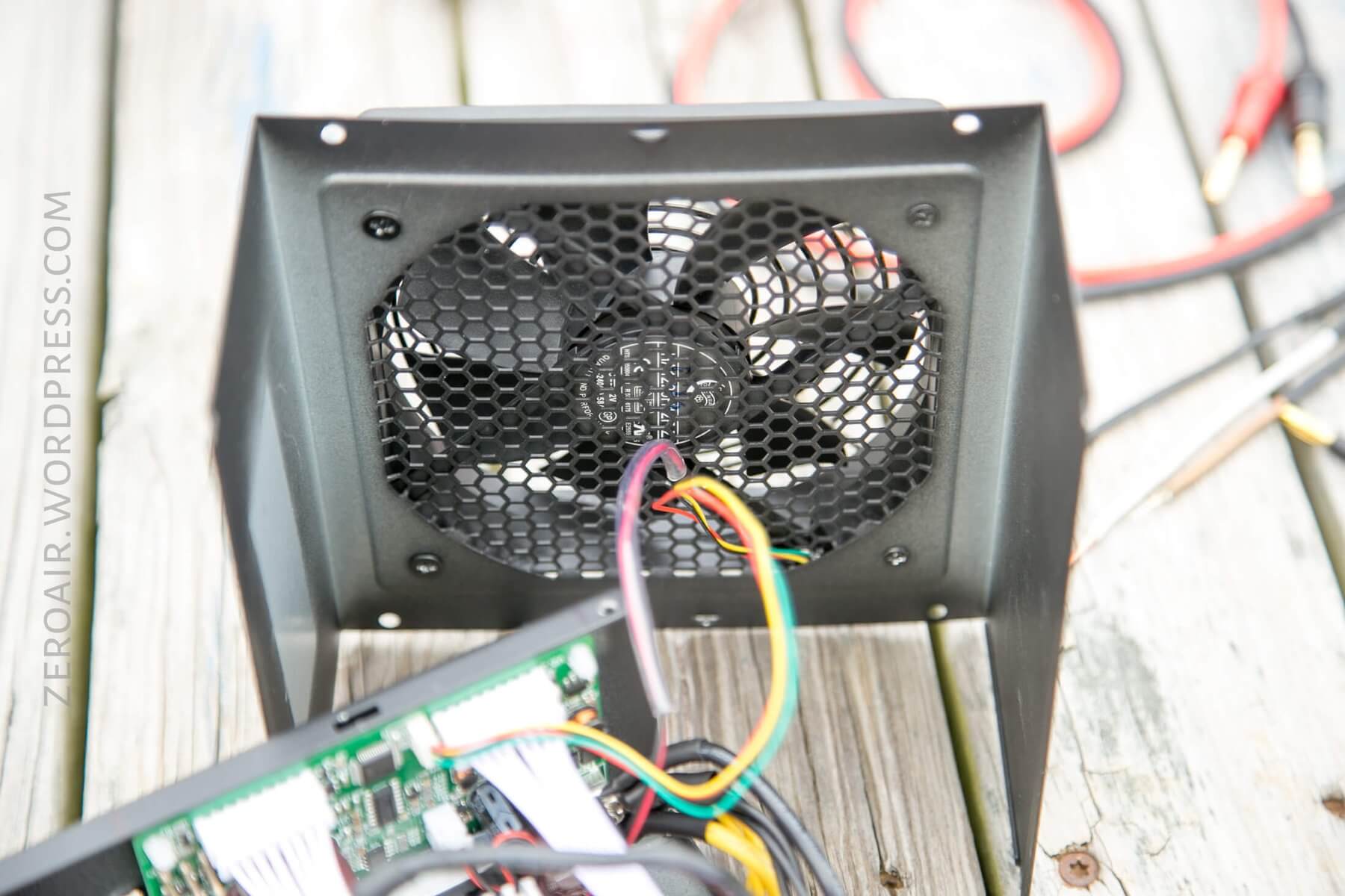
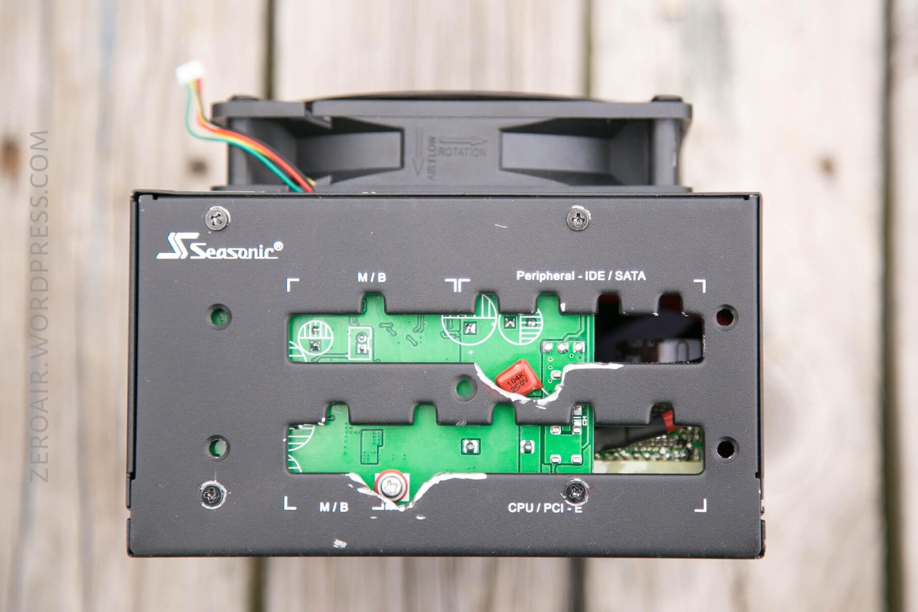
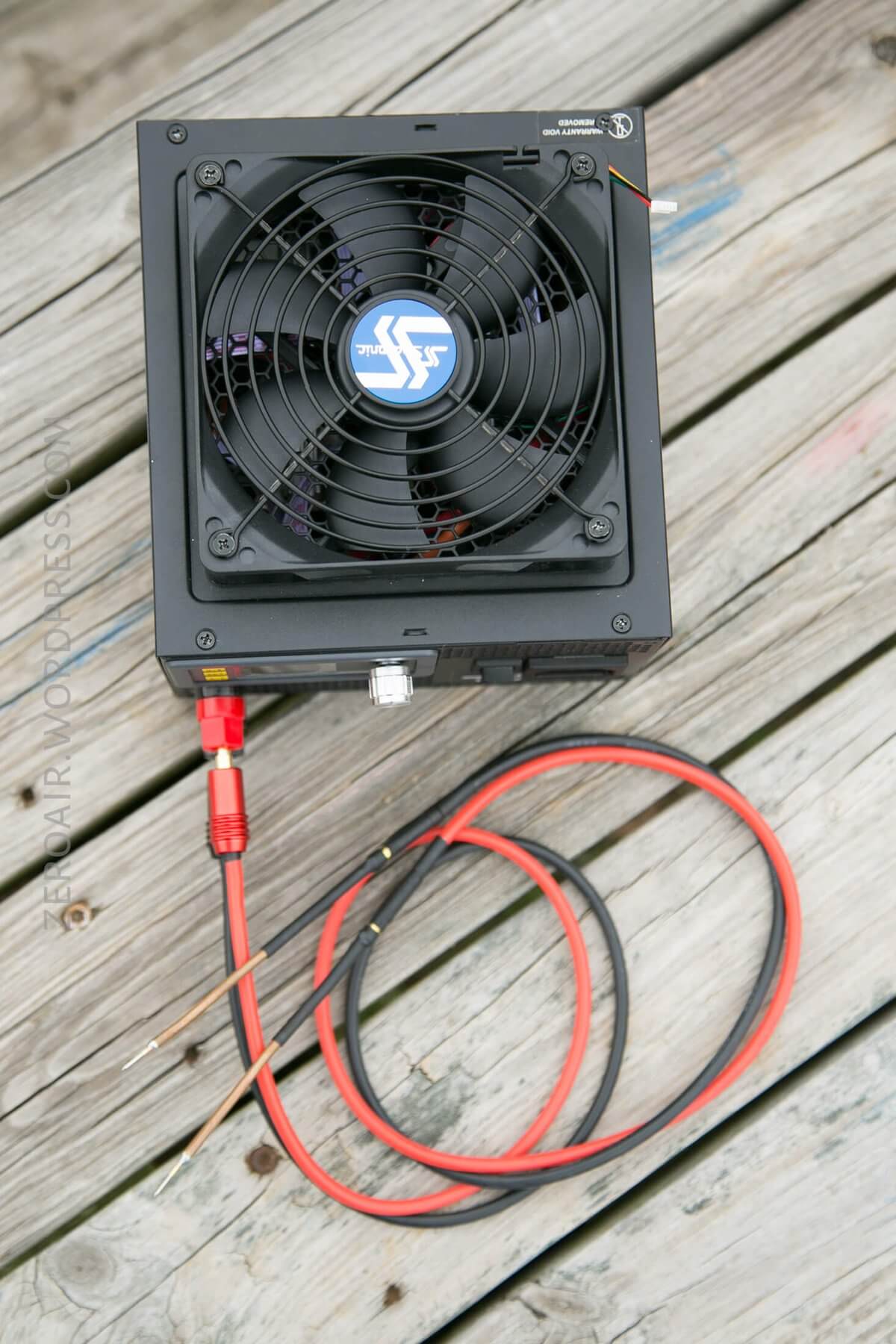
The only change I had to make that really affected the size was to move the 120mm fan from the inside of the case to the same screw holes, but on the outside of the case. Not that big a deal, and ultimately it provides a nice place to grip the unit for transport.
Power
The input power on this device does not change. It accepts wall power, so 110V. That part of the ATX power supply is exactly the same as if using it for your computer.
The more interesting part of this build is the power that we can get out of the device.
First of all, know that there are some limitations. An ATX power supply typically provides three voltages for a computer. There’s 12V, 5V, and 3.3V. There’s usually a -12V, -5, and a sense wire, and some random other stuff that generally you won’t have to worry with. Here’s a pinout for the wires, which is the same as saying “this is what the power supply supplies”:
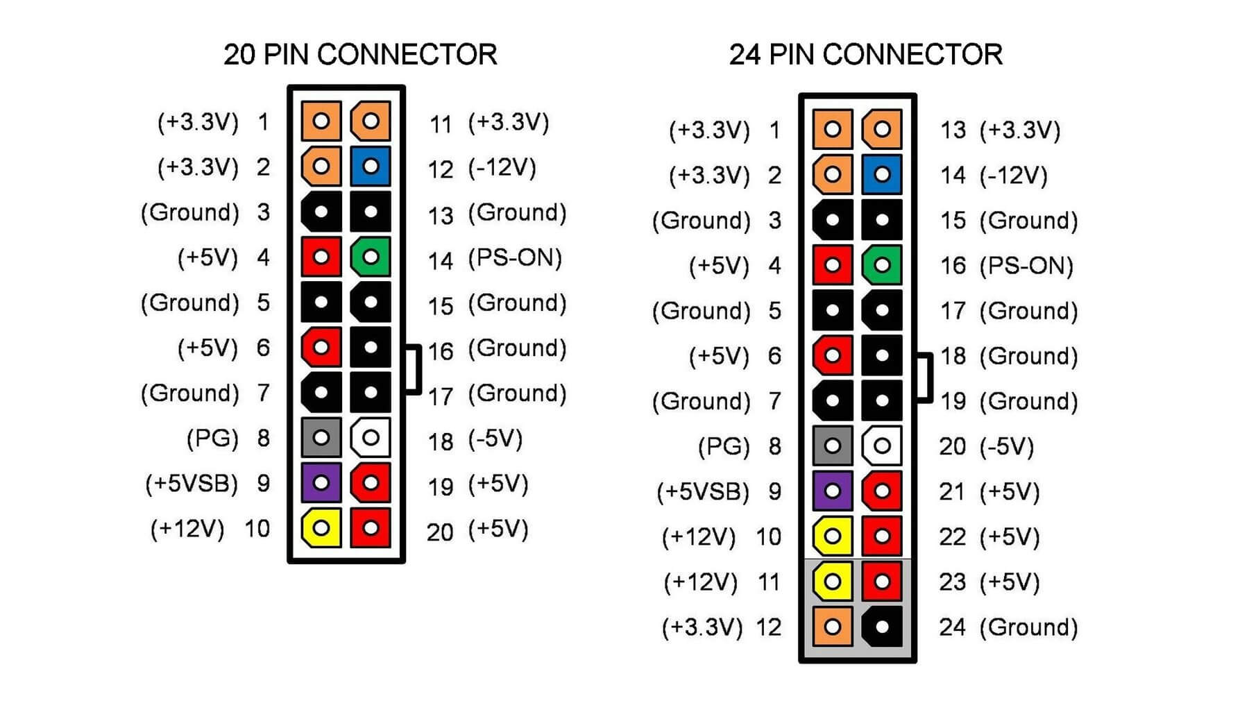
That image is from Makezine.
What we’re interested in specifically is the 12V rail. In my original design, I used 5V and 3.3V, too, but I haven’t found those useful in real life. I’ll tell you later how to use those if you think you’ll need those voltages.
Here’s the limitation: The RuiDeng 5020 is a buck converter. It can only step down voltages. That means we will never get more than 12V out of our system. There is one buck/boost module, the DPH5005. This can boost the voltage, but there’s still a limit: You’d need 28V input to get 50V output. So our 12V input still couldn’t reach the full 50V range of the 5005 device. I opted against this model because the higher amperage of the 5020 was more important to me than the higher voltage of the 5005. (To decipher these modules, note that the first two numbers are max voltage, and the second two are max current.) 5005= 50V 5A. 5020 = 50V 20A. (Maximum, with ideal inputs.)
With this limitation of our ATX power supply, and using the DPS5020, we know that we will never get more than 12V output. And it’s really 12V – losses due to inefficiencies. I am ok with this, and for my flashlight and related hobbies, this has served me extremely well.
Some might ask, could we connect the 12V rail and the -12V rail to get a total of 24V? Yes, you could. The problem with this is that the negative rail is usually rated for very low current (in my case, I believe 0.5A), and if you use the 12/-12, your max current will be the lesser of the two. So setting the system up this way was not for me.
Build Log
I made a bunch of build timelapse videos, too. Not sure how helpful they’ll be for anyone. I’ll try to give a bit of a rundown of each video, just below the video!
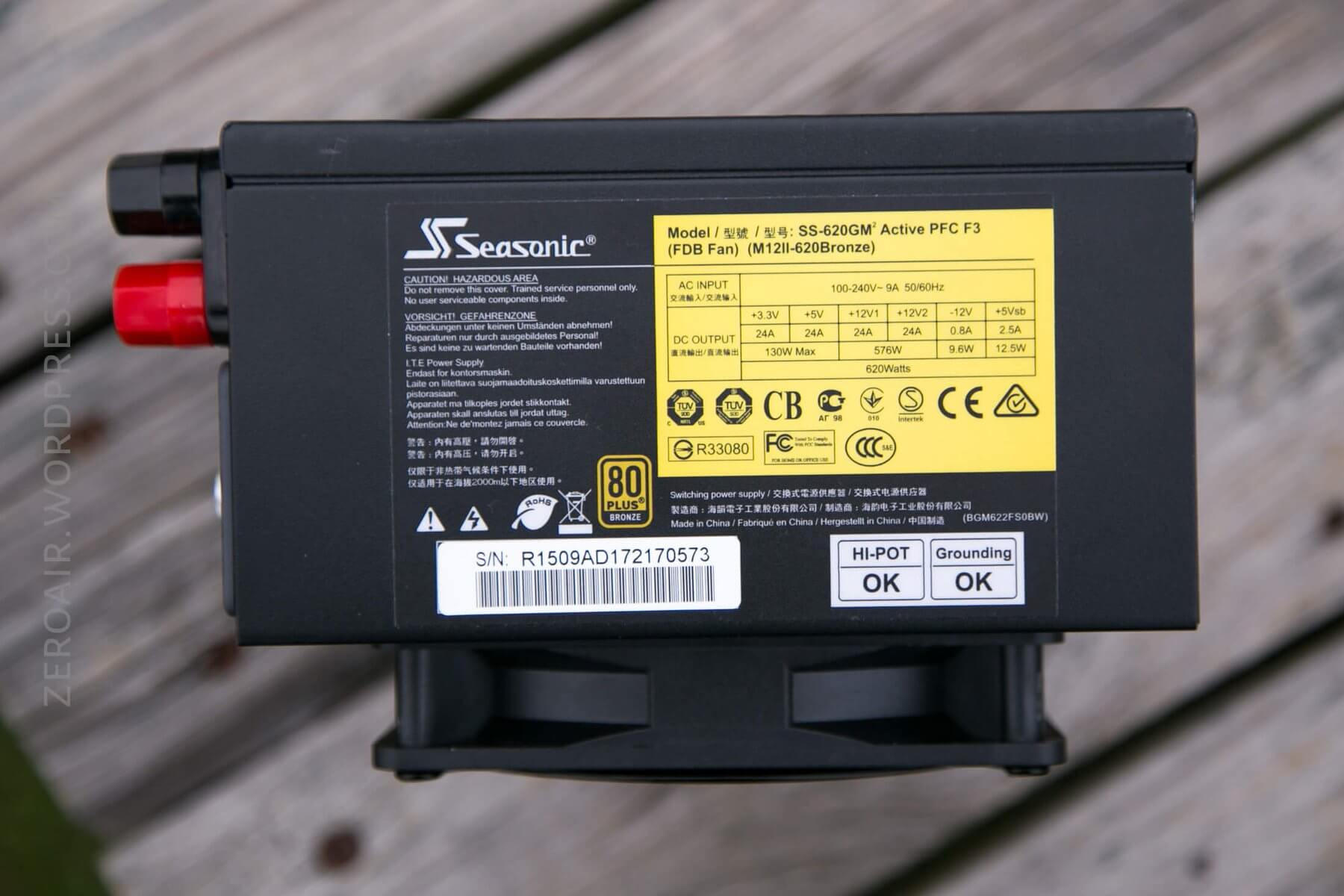
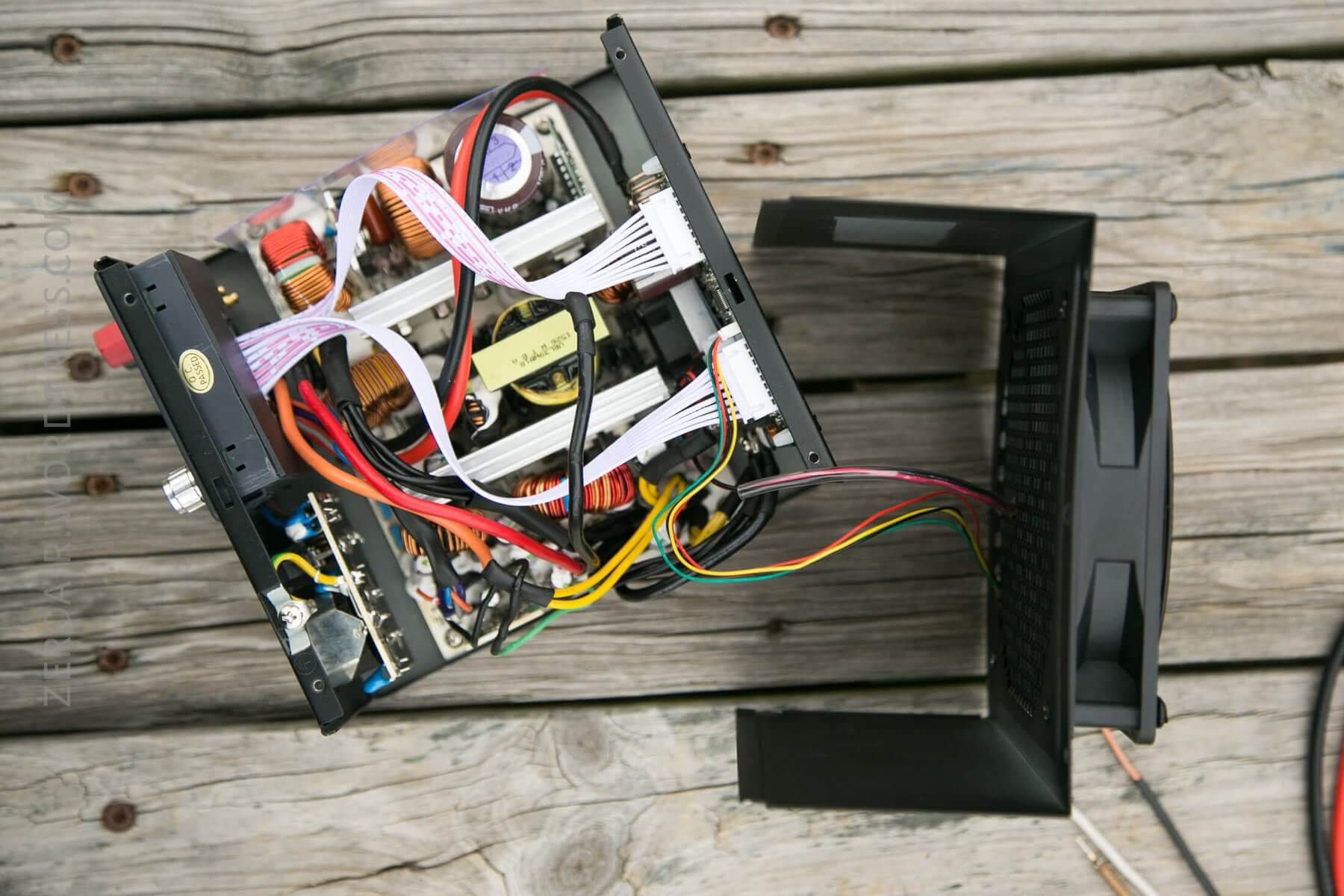
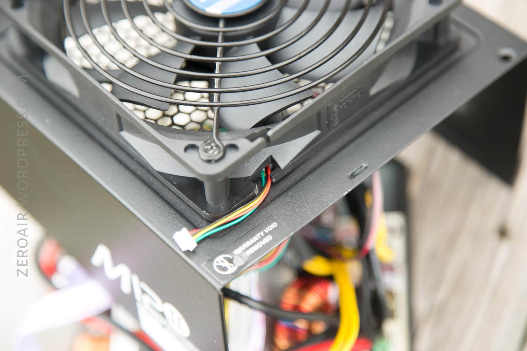
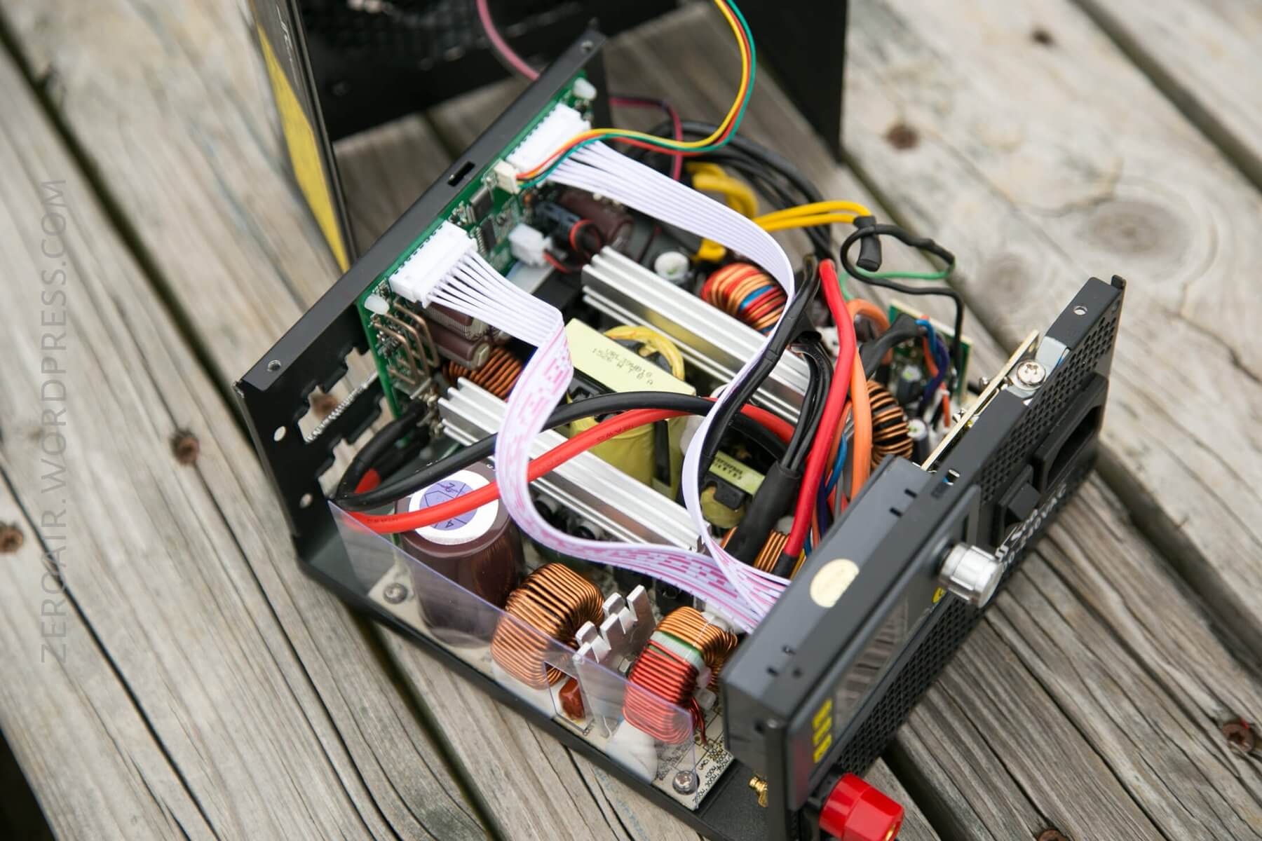
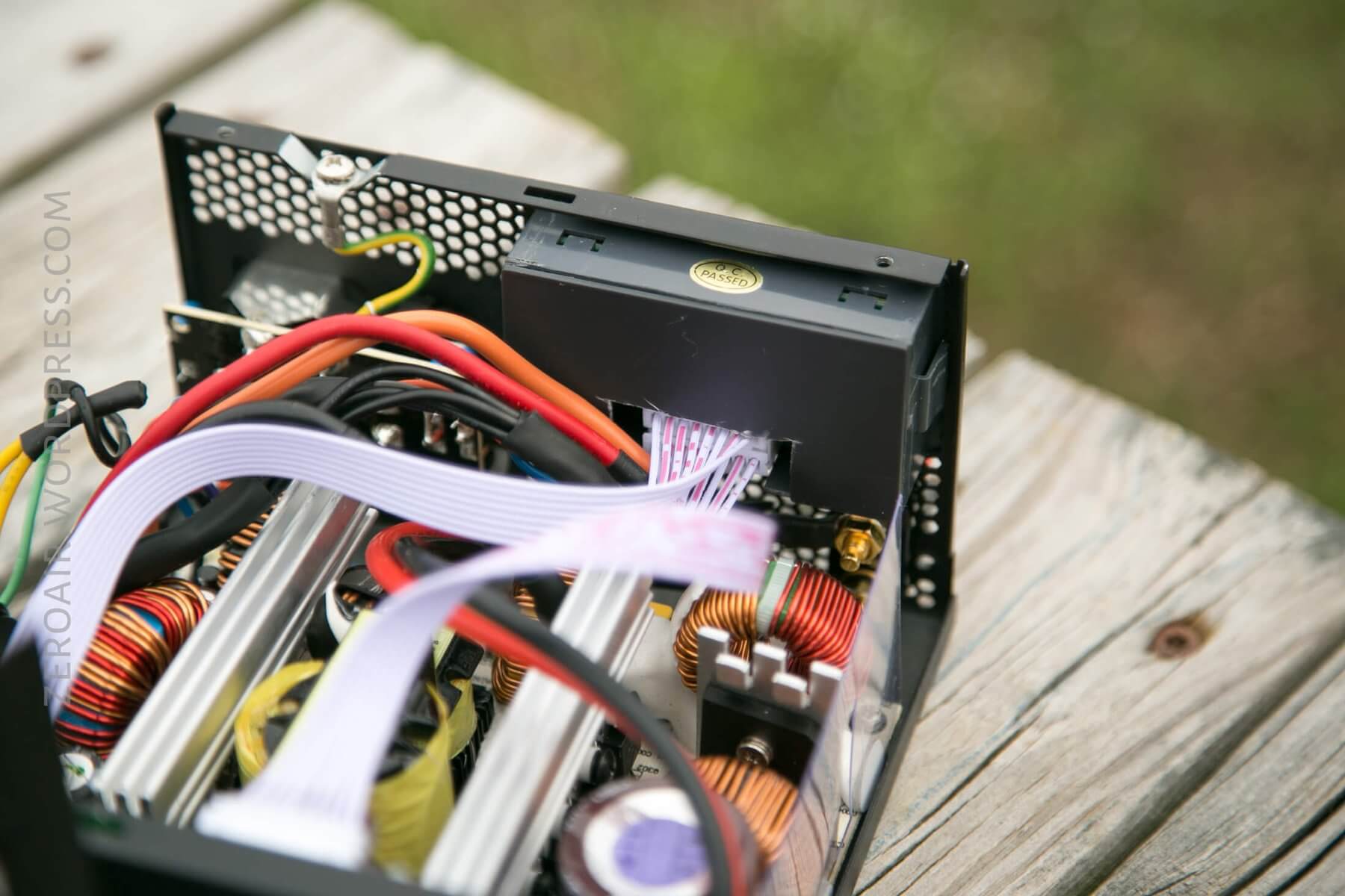
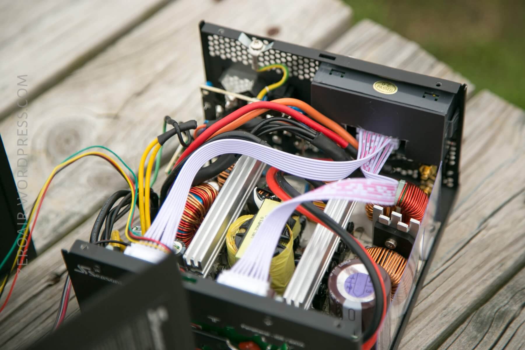
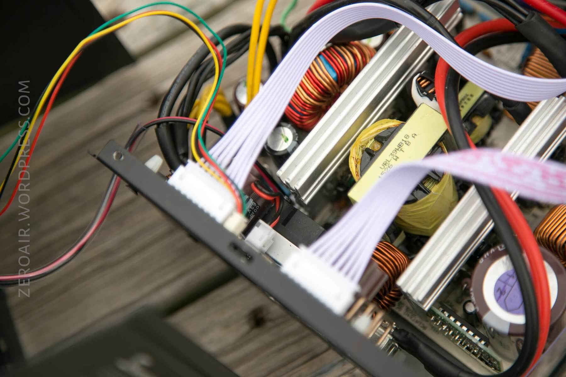
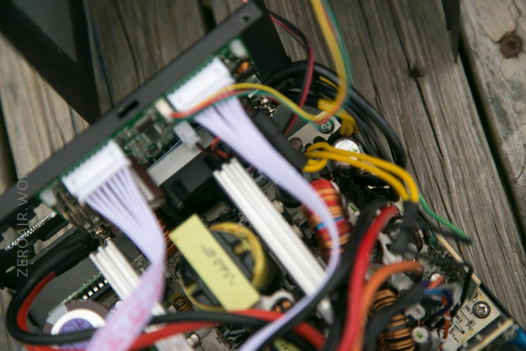
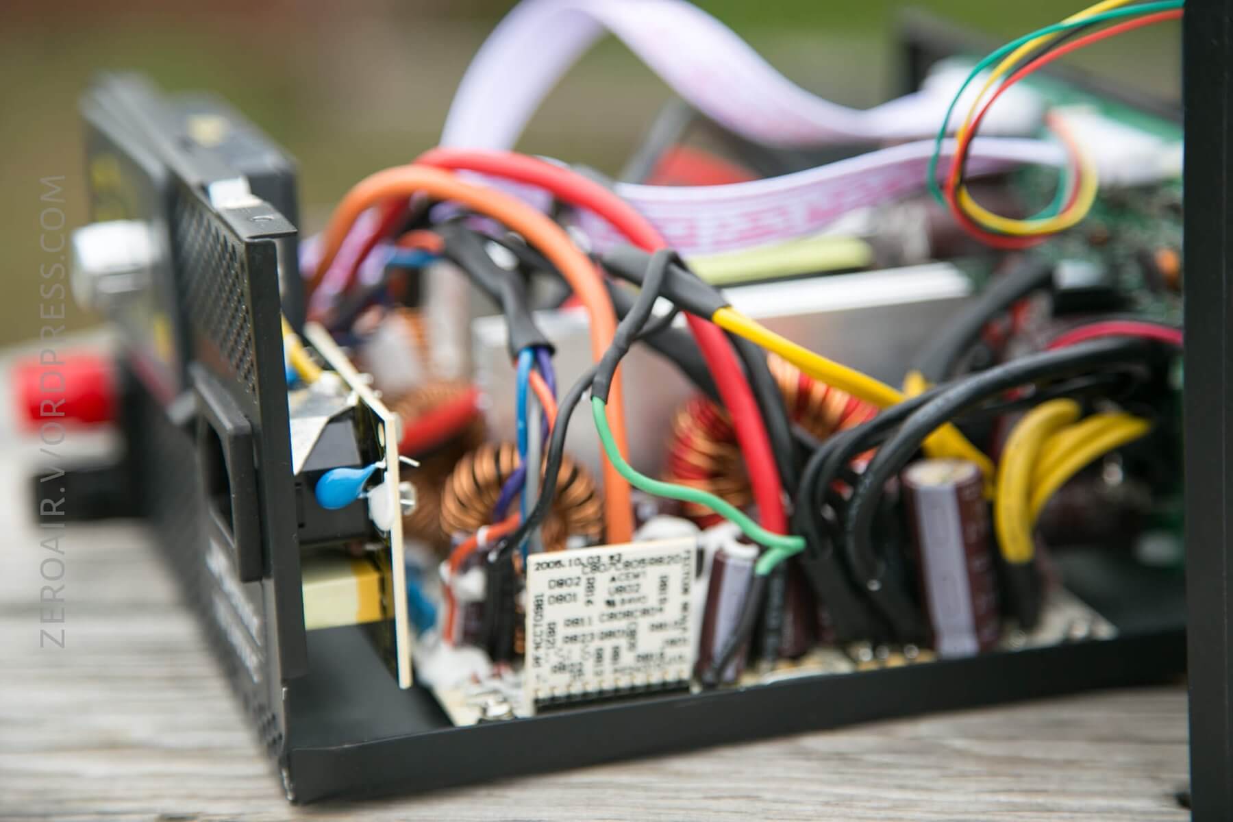
I’m just breaking the PSU open here and taking some preliminary parts off. Note that yellow sticker. You’ll want to have a good look at the PSU you use to see what power can be obtained from all the different voltages. In my case, there are two 12V rails, each capable of 24A. (In truth, these are likely not independent rails, but since I can’t use over 20A anyway, this isn’t a problem. It really just means that this PSU is more capable than I actually need. It was free, so that’s fine.) When you disassemble, you’ll have to disconnect the fan. This is a fully modular power supply, which means there are no loose wires coming out like with many of the older power supplies. This actually works out fantastically for us, since once that modular plug board is out, that gives us some extra room. It’s ok to just clip all these wires free – we won’t be reusing this board. At around 0:45, you can see what we’ll put in its place. At 0:46, I point out a resistor that is important – this indicates whether you have the new version or the old version of this board. The old version was not safe – you can find videos about that yourself. But the new version (the one pictured) has an appropriate safety measure added, which I’m pointing to. Those little plastic standoffs, which are included with the 5020, will be used, but we have to modify them. At their stock height, they don’t allow for the 5020 to fit where we want it. My first run, I actually sanded these things shorter by a few mm. This time (and in the video), I carefully sliced them with a razor blade. Much better. Finally, I show some fitment concerns. One, the large heatsink in the PSU – part of that will have to go. And also a tip for fitment – I’ve used a screw and some nuts to approximate my height, so I can test fit more easily.
Time for some modification. The display unit of the 5020 is just a little too deep for what we need. I cut about 5mm off, all the way around the back. I used those fantastic clippers for this procedure.
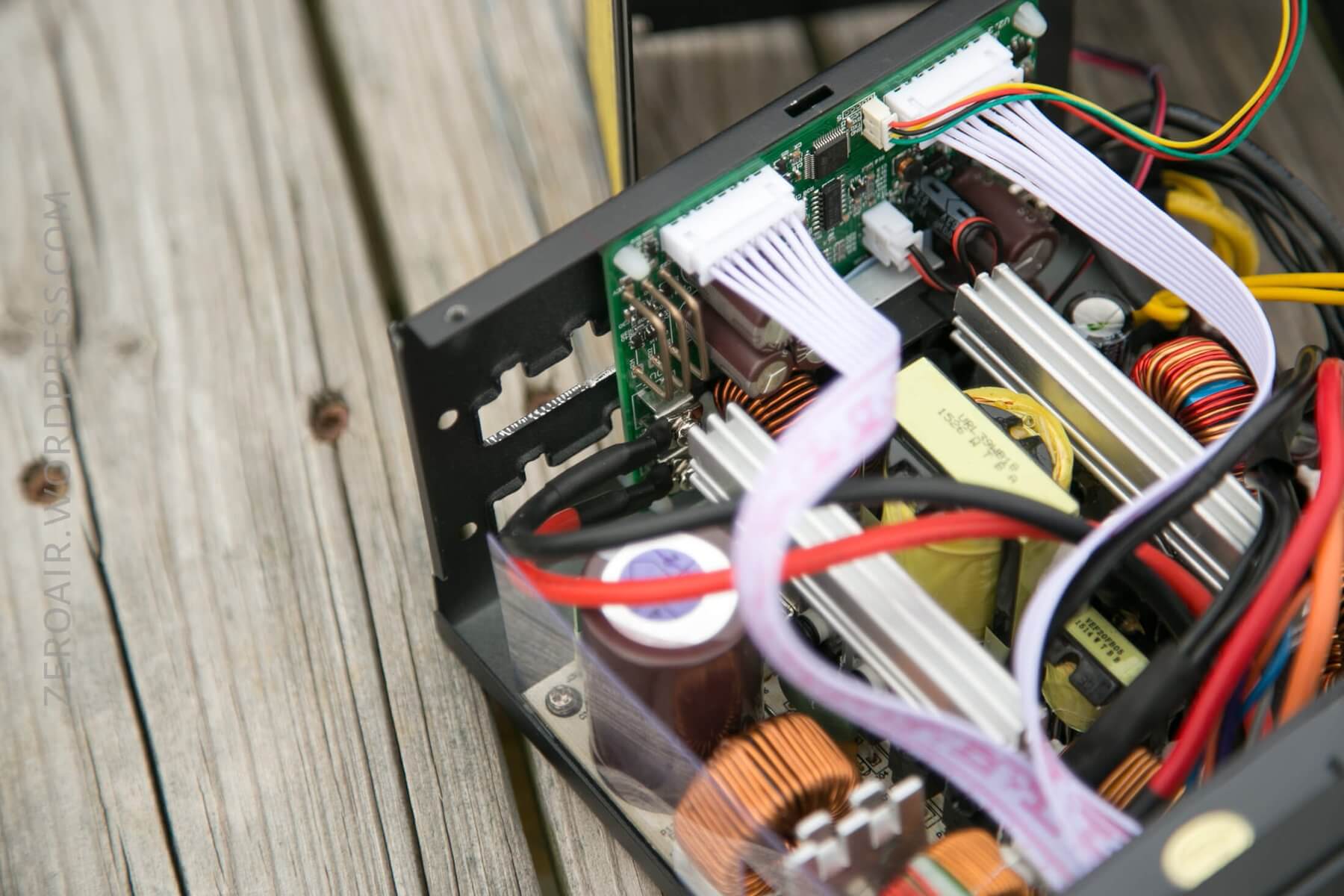
And on to probably the worst part of this job. Cutting a corner out of that heatsink. Ideally, that whole thing could come out and just be cut with a hacksaw. It’s connected to a bunch of MOSFETs, and I didn’t feel like dealing with taking them out. So I just covered the internals as well as I could, and did my best with a hacksaw within the case. Ultimately, I did take the guts of the PSU out, but still left the AC voltage bits connected (so it was never fully free). Of course, do your best to keep metal shavings out of the PSU! My advice is to cut more than you think you should. You really don’t want to have to cut this thing twice. Some metal snips might work well in this scenario, too – I just didn’t have any!
On to the fun part: Getting the display inserted and the banana plug binding posts installed. The honeycomb of this particular PSU makes cutting these openings very easy. Just snip snip snip, well short of what you need. Then ease into a fit. Remember that the display has tabs, and you’ll need to cut those separately (deeper, that is). I filed these down with a small file. This is just a bunch of trial and error, but mostly straightforward. Just don’t overcut! Remember the tabs!! It’s worthwhile to do the cut in as big a single cut as possible (measure a bunch, cut once) because then you can reuse this honeycomb in other parts of the project (particularly the back, for protection). I’ve also grouped the wires according to voltage. I’ll reuse this image from above:
That these two are “20 Pin” and “24 Pin” connectors doesn’t really matter. Have a look at the colors. Almost always, these colors mean the same voltages. Most importantly for us:
Black = Ground
Orange = 3.3V
Red = 5V
Yellow = 12V
There are some other non-trivial interests, however. The negative rails include -5V and -12V. Since we’re using an adjustable voltage setup anyway (the 5020), we won’t have to combine any of these negative and positive voltages to obtain non-(3.3/5/12)V’s. But it can be done. For example, if we were to connect the 12V rail and the -12V rail, we could get 24V out of this PSU. However, the output current will be limited to the lesser of the two rails. In my case, that’d be 0.8A. An order of magnitude lower than I want. So that’s a nonstarter.
Even so, there are important wires to us. Notably, the Green wire – we’ll cover more later, but note that it’s the “PS-ON” wire. The PSU will not power on unless this green wire is connected to ground.
And in fact, here’s me connecting the green and ground (black). I do solder them together, and so the PSU will now always turn on, without a computer connected. Normally (where “normal” is the PSU being used to power a computer), the computer will send a signal to the PSU over this line and say “it’s ok to start,” and the PSU will start.
There is probably a better way to do this connection, and if I build again, I’ll do it this way. I’d wire a DC switch between green and black, and mount it to the front. Yes, it’s duplicating switches, but it’s a nice backup. Of course, that means one more hole in the front of the PSU, but it’s probably worth it.
I’m marking the back of the PSU for the holes where the 5020 board will be mounted. I tapped the holes with a punch, then drilled small holes, then bigger holes. Since the 5020 board doesn’t leave much room for error, the placement of these holes is critical. I toyed with the idea of adding a 5V fan (~80mm?) to the back of the case for three reasons. One, it’d be nice to have extra cooling. Two, it would be nice to use a fan plus a nice grille as a cover for all the holes I wanted to put in the back of this case. And three, I would run this by connecting power directly from the 5V rail. The fan would be on all the time, and has a low (but present) resistance. Some users report the need to add a resistor to the 5V rail in order to have smooth power. I didn’t test if I have smooth power, but I haven’t had any issues without adding said resistor.
You’ll have to connect the power from the 5020 board (in back) to the binding posts that you add in the front. I’ve used some silicone-coated, 12-gauge wire, which I absolutely love. I used it inside the case (here) and also for my leads, of which I’ve made many. I use a spade connector on one end, and a ring crimp terminal on the other. The ring must be able to fit over the back of the binding post. Heat shrink everything!
Also, and probably very important to note. The binding posts I am using here are not insulated. So the posts go through the metal case, but could conceivably touch the metal case, which would be a problem. I used a couple of nylon washers around the binding post, cut to just fit in the opening of the PSU honeycomb. There could be better ways, and I encourage you to explore those and let me know what you come up with. Once the binding posts are tightened down, I have fairly good confidence that these nylon washers will stay in place, sandwiched between the plastics of the binding post.
I hope this video wraps it all up!
Right off the bat, I’m capping my 12V wires with some ring connectors (crimp and heat shrink!). Then (finally!!) dropping the 5020 board into its home, and connecting all the wires. Be aware of how the wires connect – in and out, and such. Don’t…. do it backward, or you’ll ruin all your hard work. Don’t over-bend the 12V-in on the 5020 – this has been a problem (and was the main fault of the old units). Be aware of where there might be heat in the PSU, and try to route your wires away from that.
A note about the wires that connect the 5020 board to the 5020 display. These are flat ribbon cables and can be subject to interference. My first build had the 5020 board flipped, and the way the cables were routed went over something that caused huge electromagnetic interference. I solved this by buying a second set of these cables, connecting them with the Arduino-style connectors. This worked…. but not ideal. In this build, the orientation of the rear 5020 board naturally routed these cables away from the EMI, and so it wasn’t a problem. Because of this, I recommend testing EMI before you drill your first hole.
And that wraps up the build! Don’t forget to connect your fan. Speaking of fans, somewhere along the way, the 120mm fan of the PSU got moved to the outside of the case. This is as simple as just unscrewing it on one side and moving it to the other. This also gives a good place to kick out the connectivity options of the 5020 – I have both Bluetooth and microUSB. Unfortunately, they can’t be connected at the same time, so take your pick.
User Interface and Operation
I’ll be honest – this isn’t a review of the RuiDeng 5020, which is essentially the user interface of this device. I’ll summarize by saying that the user interface is pretty good, and I have no trouble using it. I can run through the user interface in another post if there’s interest.
How to use the device (not just the software)? Well, start by plugging in some of the custom wires that I’ve made (which you can see below). Red is positive, and black is ground. Then I attach whichever tips are most useful for the application. When I’m testing low voltage protection (LVP) of a flashlight, for example, I’ll choose the spring tip tips. Then, power the device on, set the voltage and current on the 5020, and turn it on. Then connect to the positive and negative of the flashlight, and go through the modes. Note that the 5020 has memory slots, so I have a “single 18650” saved as 4.2V and ~10A (can go up to 20A, I just keep 10A for ‘safety’). There are a number of memory slots, but I haven’t found the need to program more than a couple.
I’ll add that there is at least one alternative firmware. It’s called OpenDPS. It looks great, but I haven’t tried it. I don’t actually have the device for flashing firmware, and also, the native RuiDeng firmware is just fine for me. I might try flashing this other firmware if I get the device, just to see what the OpenDPS is like. If I do, and there’s interest, I’ll report on that in another post.
Future Changes/ Ideas for you
What would I change about this build? Well, most of those changes have already been mentioned. I’ll try to summarize them here.
- I’d add a DC switch on the green 5V line, so that I can have that as a device shutoff.
- I’d really like to keep the 120mm fan inside the case, and I do think it could be done…. That would take some fan modification, though (the board of the 5020 just doesn’t allow the headroom for the fan).
- It would really be nice, after all this work, to have a device that goes over 11V output. There are such devices. For example, Golf Cart Chargers are ~50ish V and >20A, which would supply everything the 5020 can handle anyway. There are server power supplies at 48V, which do the same. There are a number of options.
- The 5020 really does not have to be built into the PSU. There are boxes made by RuiDeng that fit this 5020 perfectly, and would make this whole setup just about as simple as connecting a few wires. I can describe that build if anyone’s interested!
- You could use the boost version of the RuiDeng, the DPH3205. But you’re still limited to 32V max output (realistically, less, I believe, with the 12V input). Also, that maxes at 5A output. Realistically, >5A output was more important to me than >11V output, so that’s why I went with the 5020. Also, there are versions like the DPS5005, which would be so much easier to install – it has only the display! So you could have 11V and 5A (not more), but controlled current and voltage. This could be a win for many users, to be sure. Also, it could likely be done without moving the fan to the outside of the case! And would not use even half the 12V rails, which means you could maintain a fully working PSU.
- I’d love to have added some ports, like USB/microUSB, etc., to the front of this case. At the moment, that’s past my expertise (mounting them was the real issue). They would connect directly to 5V, and be plenty beefy for any amount of current you’d want. I did purchase a part for this, but never got to connecting it.
On my teased build 6 months ago, I had four sets of binding posts. One was connected to the RuiDeng 5020 (and thus variable current and voltage). The other 3 were connected directly to 12V, 5V, and 3.3V. This meant I could always get those specific voltages without even using the 5020, at any time. I find that I absolutely do not use these, ever. So in my second build (this build), I left them off. I’m happy with that decision. Just note that either works well!
Accessories and Build
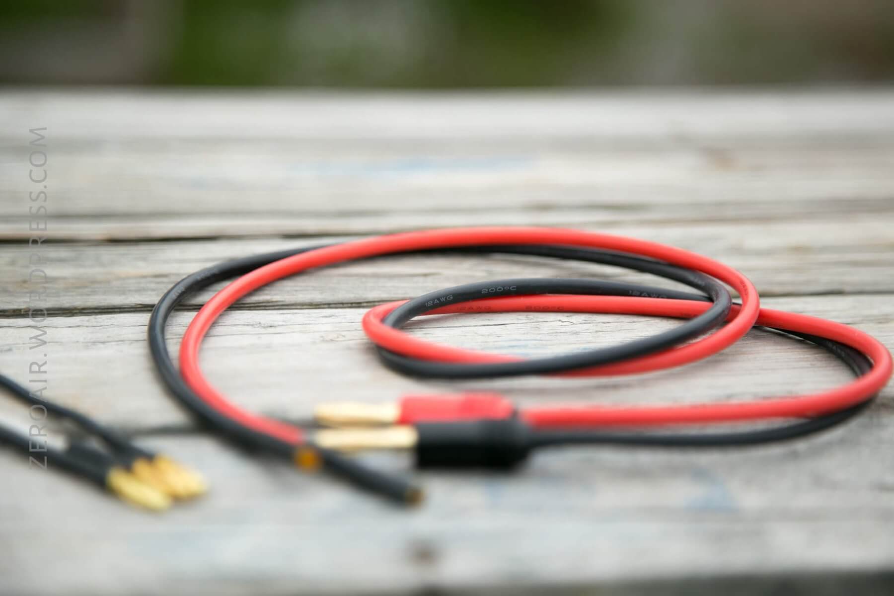
Using the 14-gauge silicone wire, I made some leads. Not simply leads, though – I made extensions essentially, and the option to connect a number of style tips. I only show two types below: Spring tip, and solid copper (wire).
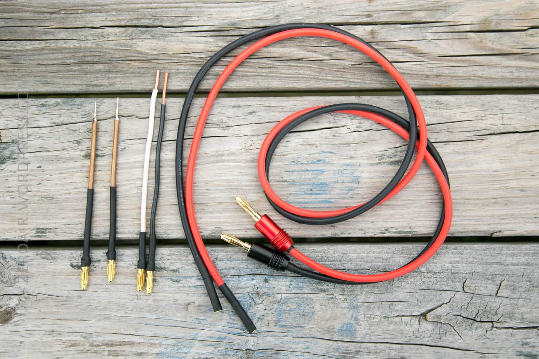
The spring tip is super nice. First off, they’re fairly sharp, so they get a nice bit of grip on flashlight parts. Secondly, they’re springy, which helps hold them on the target more easily. I didn’t build these, but I’ll offer you (what I think is) a clever tip. Start with 1/8″ copper tube! The little brass tip (from Banggood) will fit right inside this copper tube. Solder these together and boom, done!

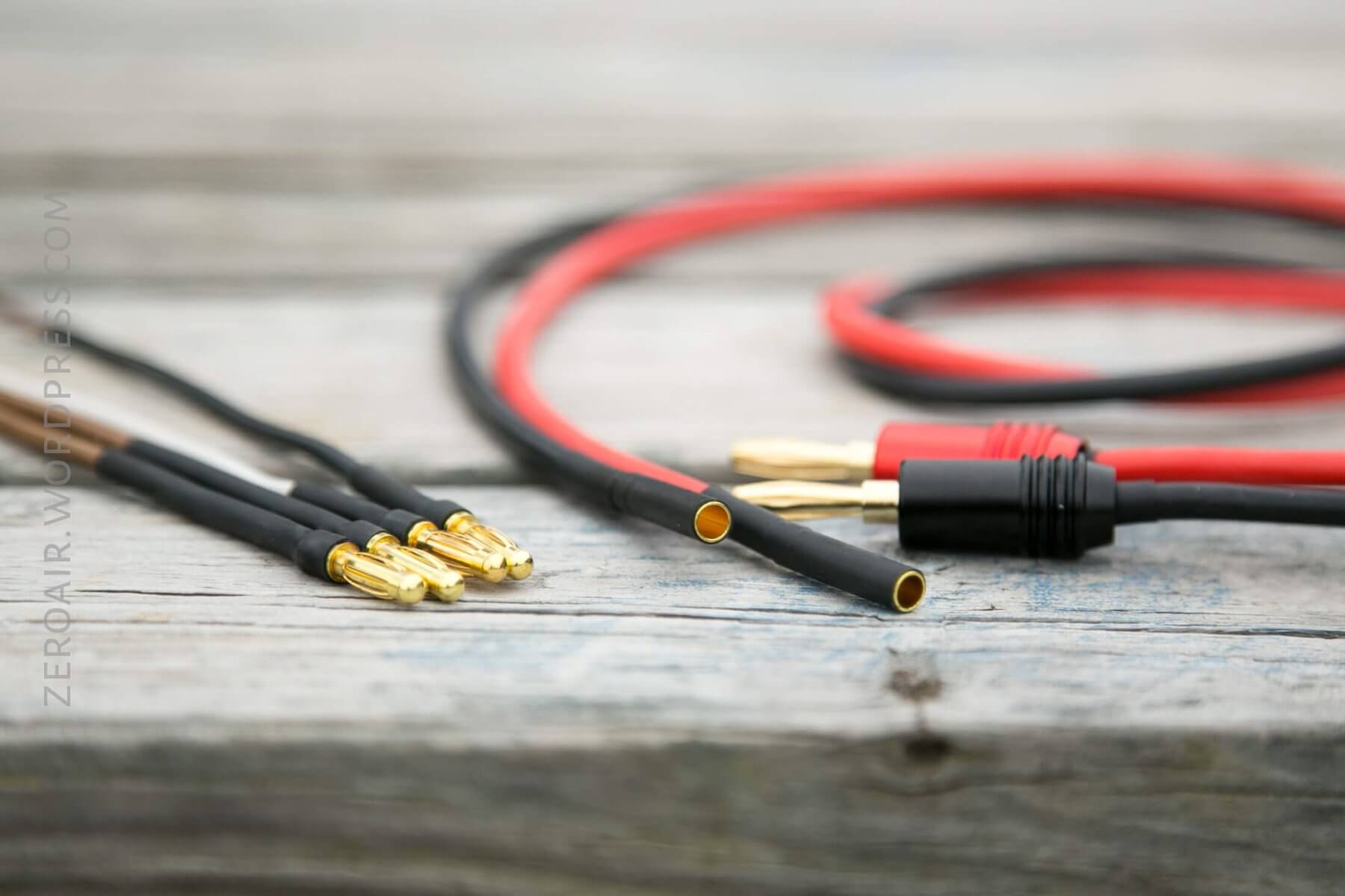
The other end of these tips, and the extension wires, for that matter, require 4mm “bullet connectors.” I can not stress my love for these things enough. Buy 20, then buy 20 more. They allow one to build so many things, and they’re so cheap. The extensions have regular banana plugs on one end (which connect to the bench power), and the other end has the female side of the bullet connector. Having a bunch of tips, with male 4mm bullet plugs, instead of a bunch of whole wires with those tips is space-saving, cheaper, and much more convenient.
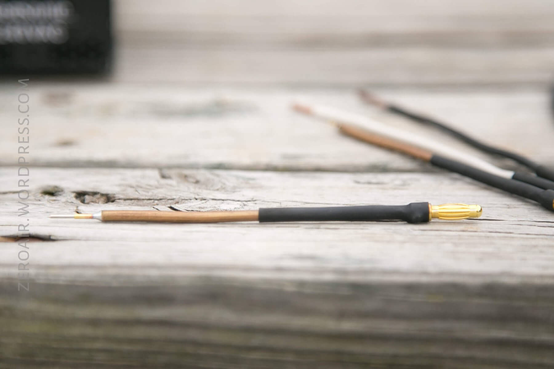
I’ve since added a much beefier tip, which is 14-gauge solid copper wire (just like the others, but about 1/8″ thick copper! I rounded the tips to a broad point with the Dremel.
I also made an extension cable that terminates in alligator clips. This is a must. They’re so useful and convenient.
Random Comparisons and Competitive Options
This no-name power supply is going to be the most competitive option, though there are definitely others. This one is nice because the range is up to 30V and 10A. That’s a very nice range indeed!
Conclusion
What I like
- It’s a working bench power!
- Adjustable Voltage
- Adjustable Current
- Possibility of 20A out of the unit
- Small overall size
- The knowledge I gained building this unit is absolutely invaluable
What I don’t like
- Max of 12V (really more like 11V with losses)
- RuiDeng software could be improved (both on the device and its computer-controlled software)
Notes
- This content originally appeared at zeroair.org. Please visit there for the best experience!
- Use my amazon.com referral link if you’re willing to help support making more reviews like this one!
- Please support me on Patreon! I deeply appreciate your support!
Discover more from ZeroAir Reviews
Subscribe to get the latest posts sent to your email.
Excellent write up, super informative!
I especially like the addition of the timelapse videos, and as always, your pics are top-notch. Thanks for posting this build!
Thanks! I’m not sure I’m done, either! Might have another build or two in me!
Very cool build! I like the idea of the small form factor. How do you usually use this in flashlight testing? Is it mainly for battery charging?
I actually don’t use this for charging at all! I’d need to add a diode to prevent reverse current back into the PSU. I’m not sure how to do that, and I don’t need this as a charger if I’m honest.
If you did need it as a charger, I have a neat setup for that; maybe I’ll make a post sometime about that. 🙂
What I use this for is testing the current used on each mode, and testing for low voltage protection.
Since this post I’ve built two little probes with switches, so I can connect power and simulate the clicky switch (of mechanical switch lights, not e-switch lights).
Thanks for the comment!
I’m still not getting it, how do you test the current when you’re the one applying the power? Does the power supply get set to 3.7V and then it automatically adapts to the current demanded by the light? Thanks!
How about I do a video showing it? Maybe I’ll make a post soon with that info. Could be useful!
I might do an updated version, too, which I think will be a much more appealing build. For now, just source the ATX power supply. I’ll tell how to do the rest soon. 🙂 (And still post a video of it being used.)
Pingback: Sinner 18350 Ready-Made Titanium Flashlight Review – ZeroAir Reviews
Pingback: Fenix E16 Flashlight Review – ZeroAir Reviews
Pingback: Vapcell 21700 Cell Review – ZeroAir Reviews
Pingback: How Do I: Install a Dragon Flashlight Driver – ZeroAir Reviews
Wow, I’ve read and watched dozens of tutorials on bench top power supplies, and this is the best one I’ve seen by a mile! Really informative, great detail, and well presented. Great work!
When I built mine I used a Ruideng BPH3205 which can take the 12v supply and convert it to 0-32 volts, 0-5.1 amps output. Great little unit, same form factor as yours. It’s nice for charging cordless power tool lithium batteries.
Bookmarked, nice site!
Ah right, the 3205. I considered that if I recall, but I valued the higher current over the higher voltage – a trade off. If there was a way to run both from one power supply. 😛
For testing flashlights, which are mostly well under 12V, mine works. But there are some lights with 3S or 4S battery that really need higher than the 11.xV mine can supply. In those cases, 32V would be plenty AND 5A would almost certainly be plenty as well.
Maybe it’s time for me to build another? (I actually have done so, but with different outcomes in mind, and with different tools.) I have a few of these guys floating around now actually!
Thanks for your comment!
Oops, I think it’s actually DPH3205
My records show that I’ve purchased a DPH3205 at some point…. I shall seek it out and maybe drop it into a power supply!
Are your (assuming you did make the supply I saw on IG) USB ports regulated in any way? Or just wired straight to 5V? I was going to add those ports but I got concerned that dumb USB ports might allow power to travel the wrong way, from device back into the PSU. Also I couldn’t find USB ports that suited me, and at the end of the day I didn’t need them….
Pingback: Zonestar Z8XM2 Multi-material 3D Printer Kit Review - ZeroAir Reviews
Pingback: Ultrafire WF-504B P60 Host/Flashlight Review - ZeroAir Reviews
Pingback: Goodbye 2019, Welcome 2020! - ZeroAir Reviews