How Do I: Install a Dragon Flashlight Driver
Many lights now have the CWF Dragon flashlight driver, but today I’m going to show you how I Install a Dragon flashlight driver! Hope this information is useful!
The build is specifically about the MechTorch and the Dragon driver, but generally building a light will be practically the same.
Raw Goods
You’ll need a few things for this build. You’ll need a host (which we covered yesterday). You’ll need a driver. The driver controls things like the modes and output levels and has in the electronics things like the UI. You’ll need an MCPCB with emitters. You may need to couple what MCPCB and emitters you get with the driver, as I did – my driver is a CWF Dragon, which is made for triples with secondary emitters, and so has specific needs (needs a triple with secondary MCPCB).
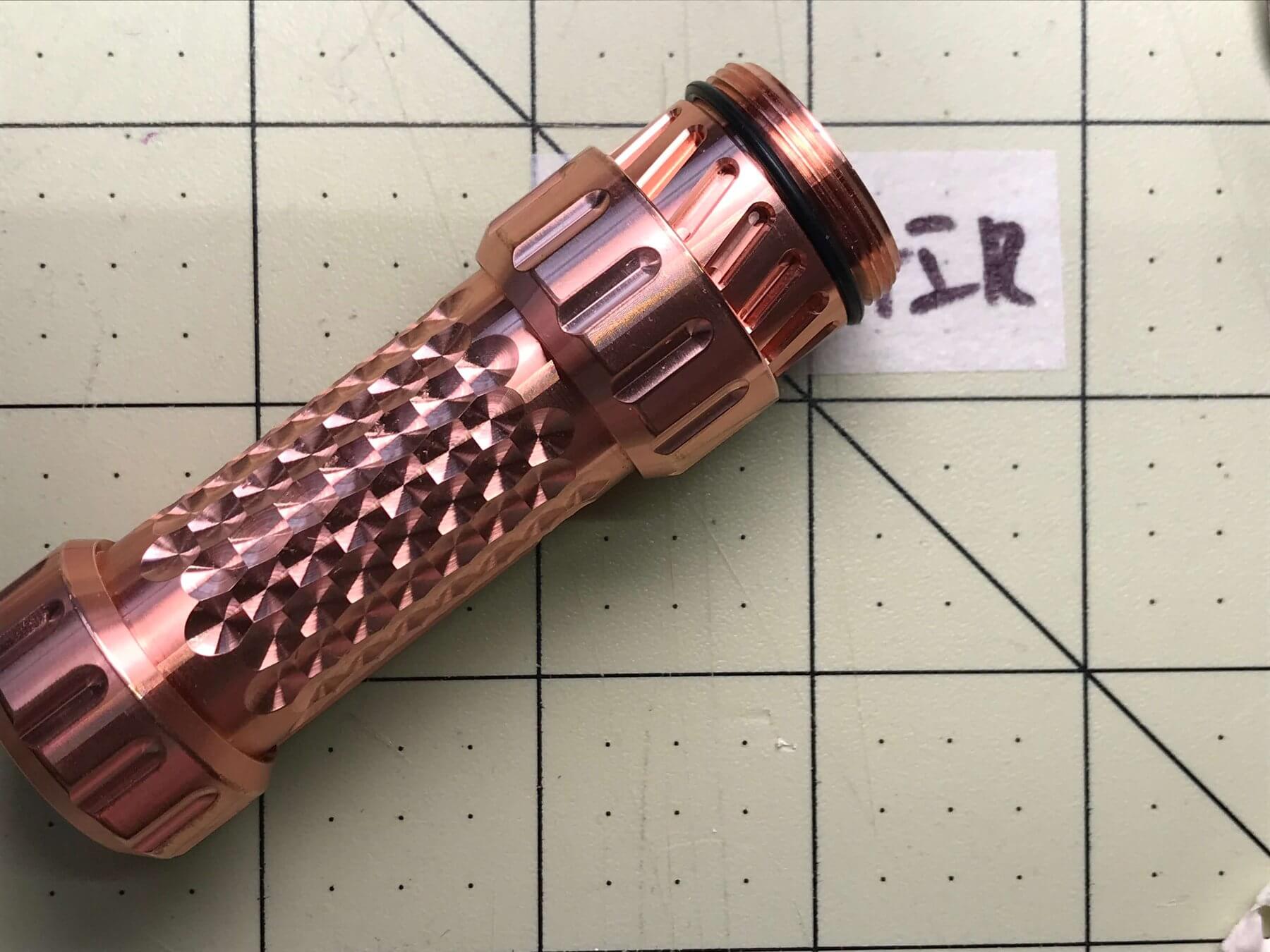
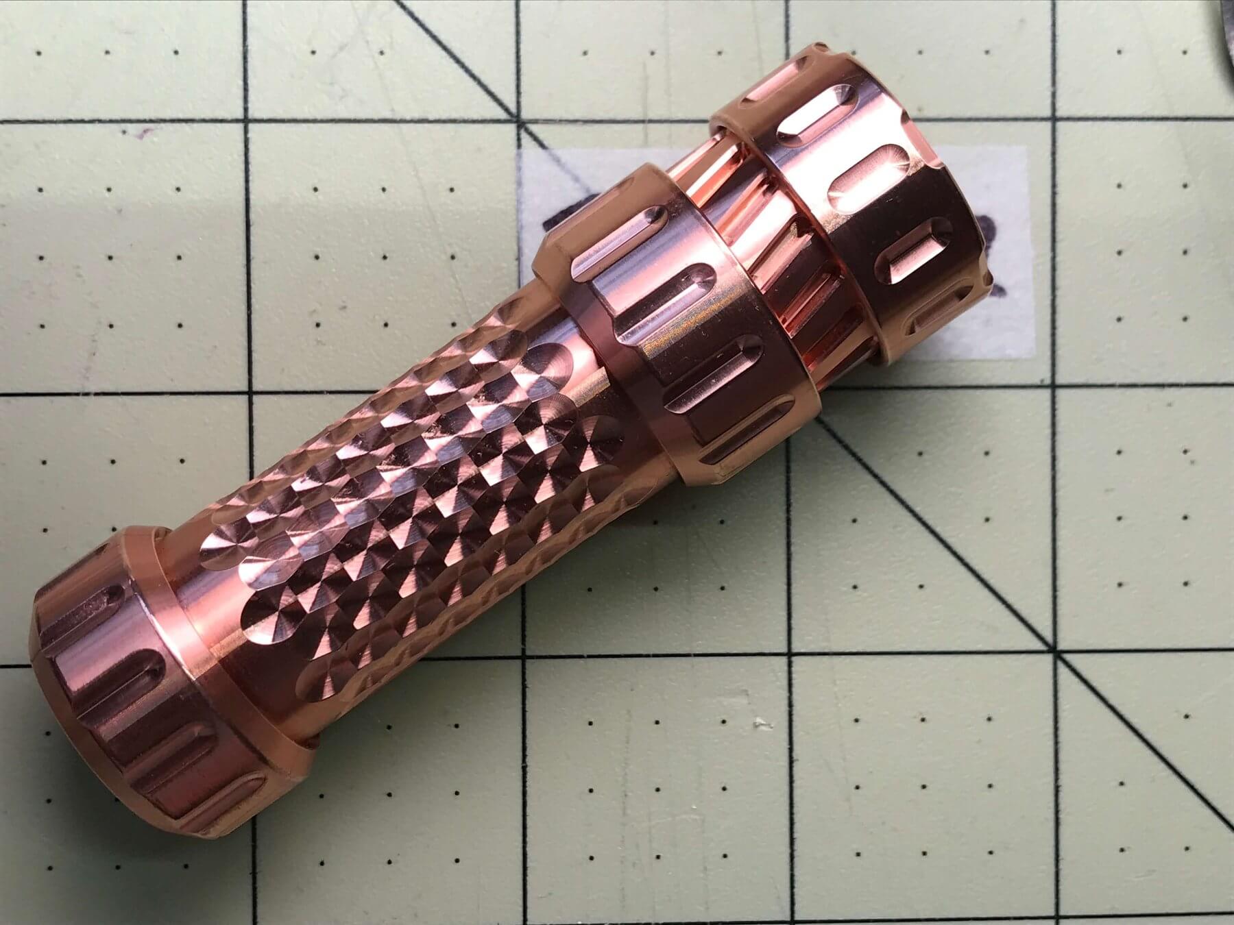
The Host
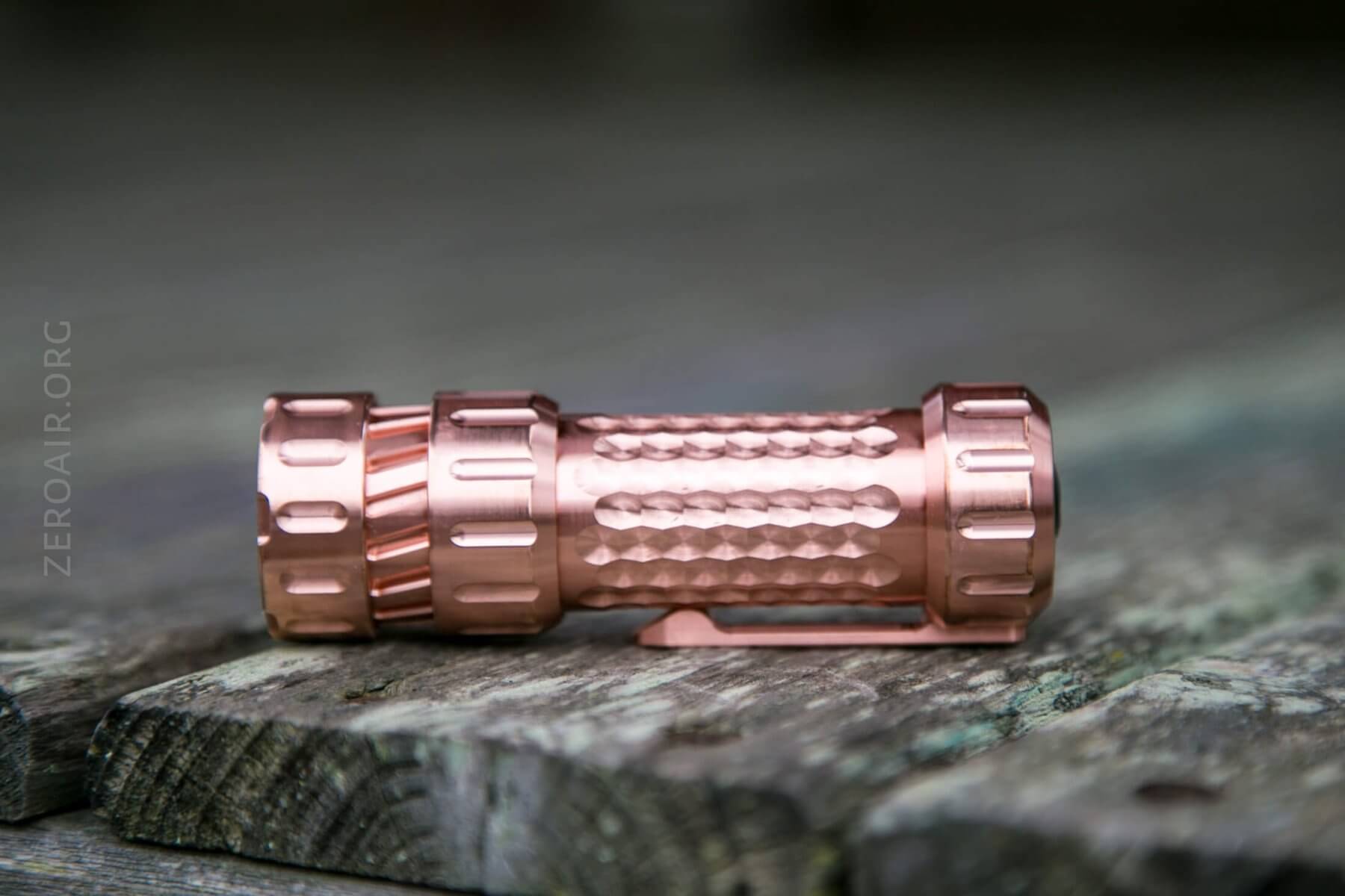
I’m using this MechForce MechTorch host for my build.
The Driver
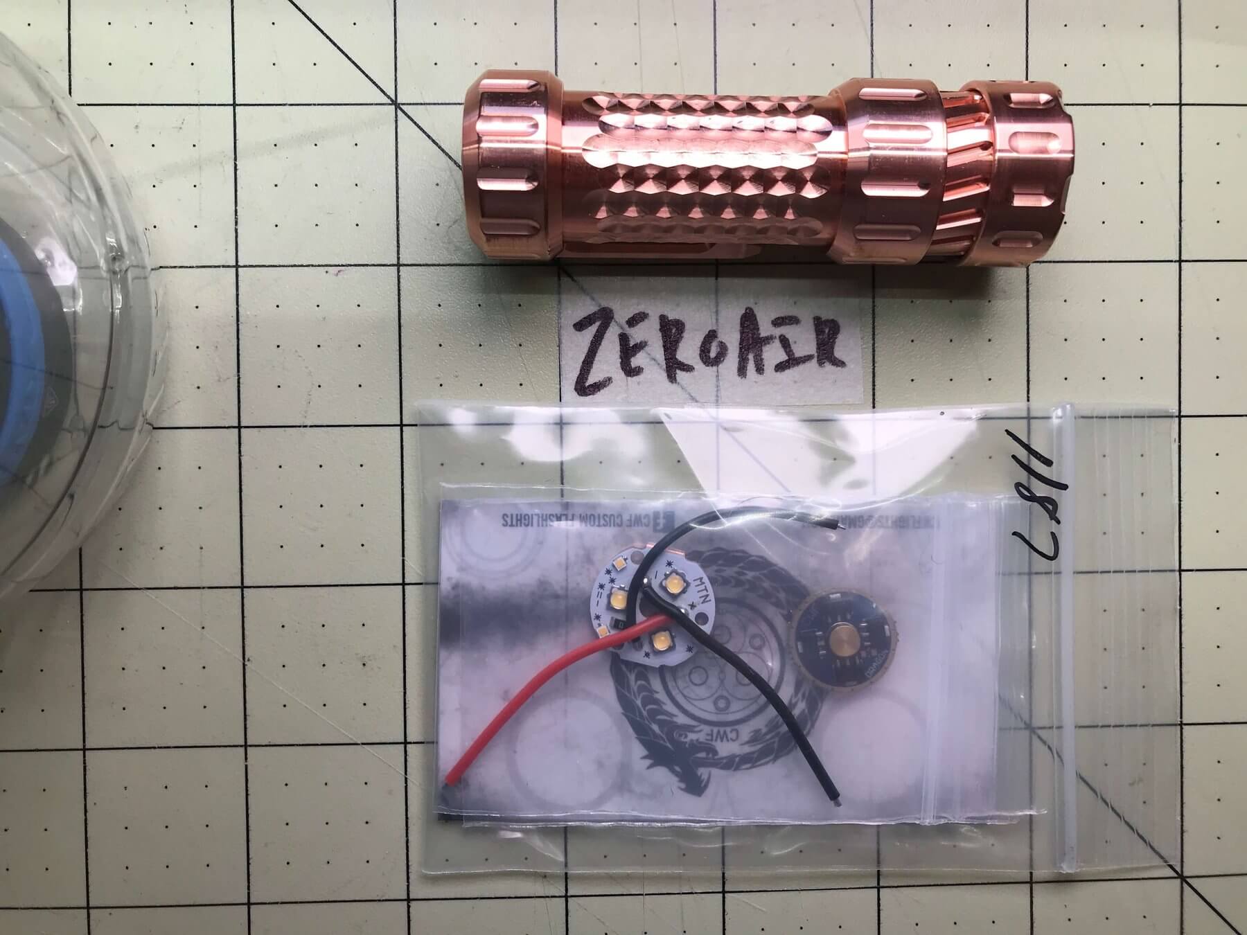
And since I’ve been very interested in the CWF Dragon driver, I’m building that host out with a dragon driver and primary emitters (Nichia 219c) and secondary emitters (XQ-E Amber) already flowed onto the MCPCB and also purchased from CWF along with the driver.
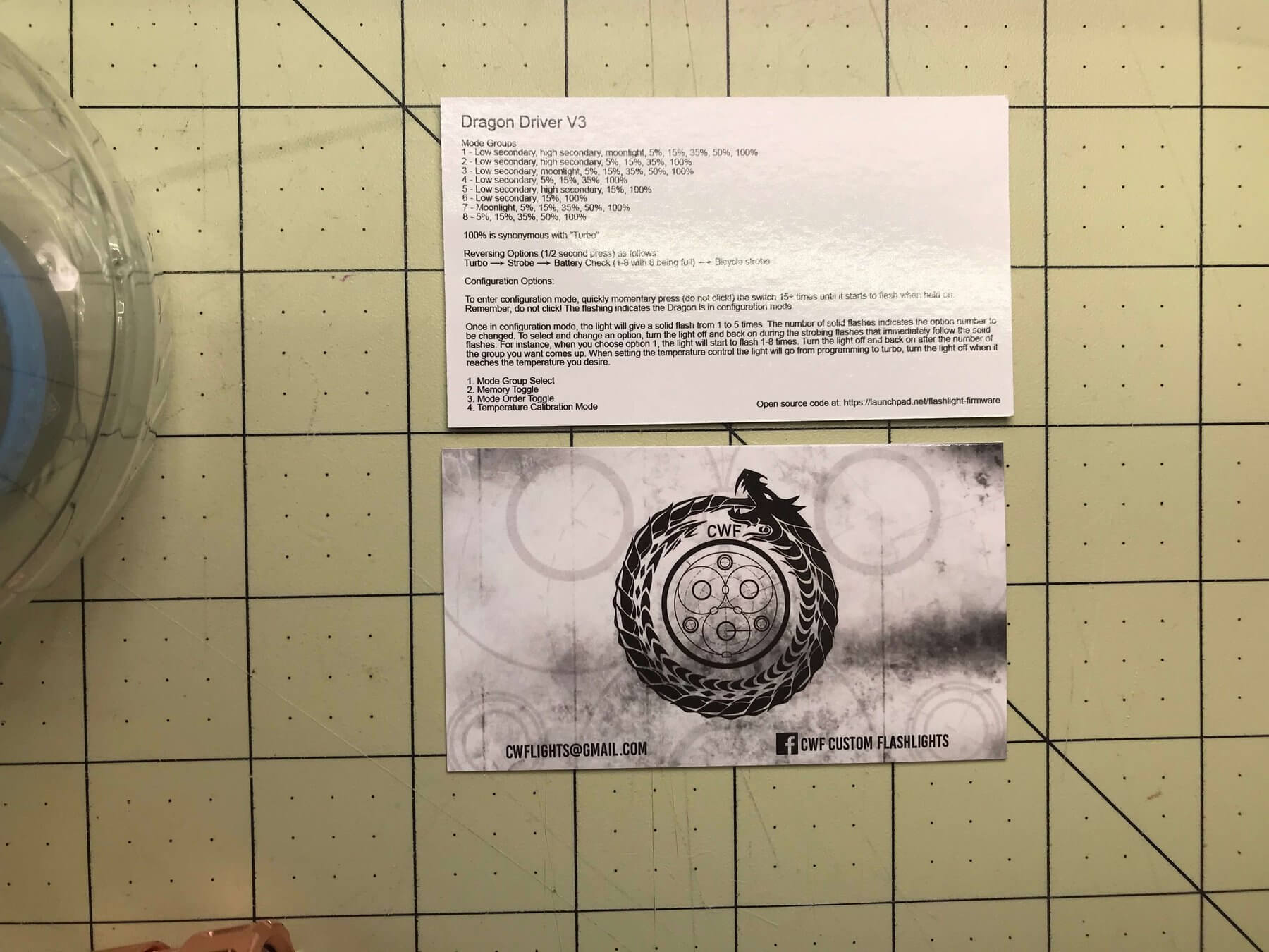
The driver comes with this card, which describes the user interface and mode groups.
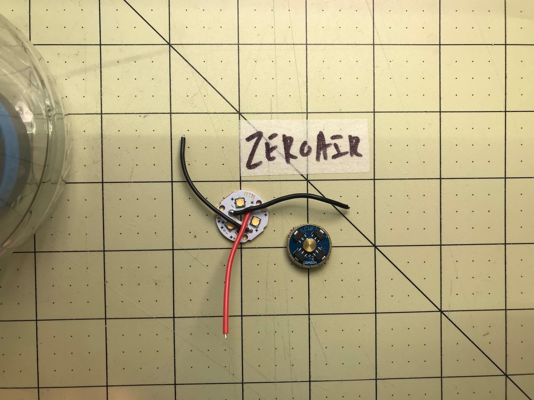
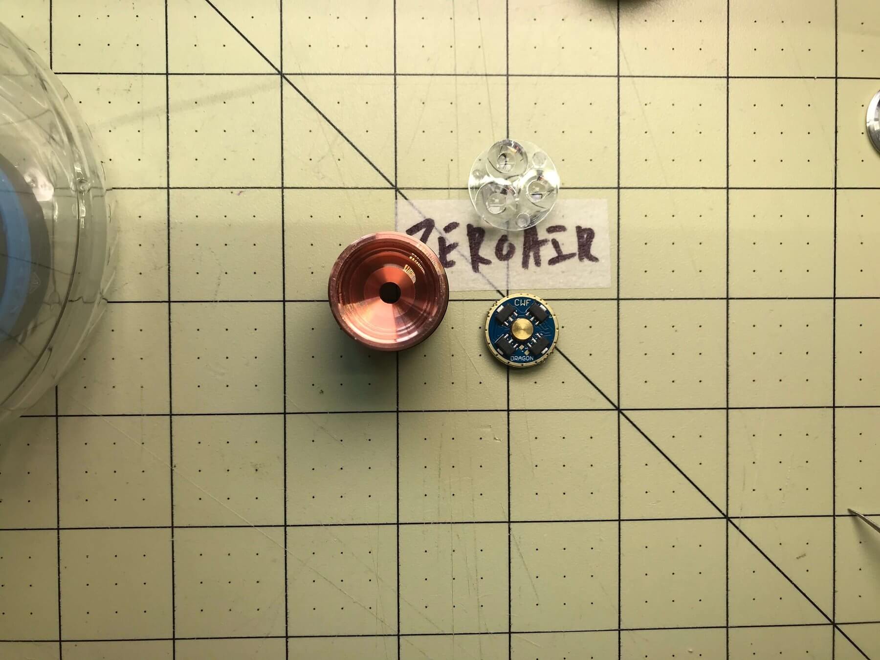
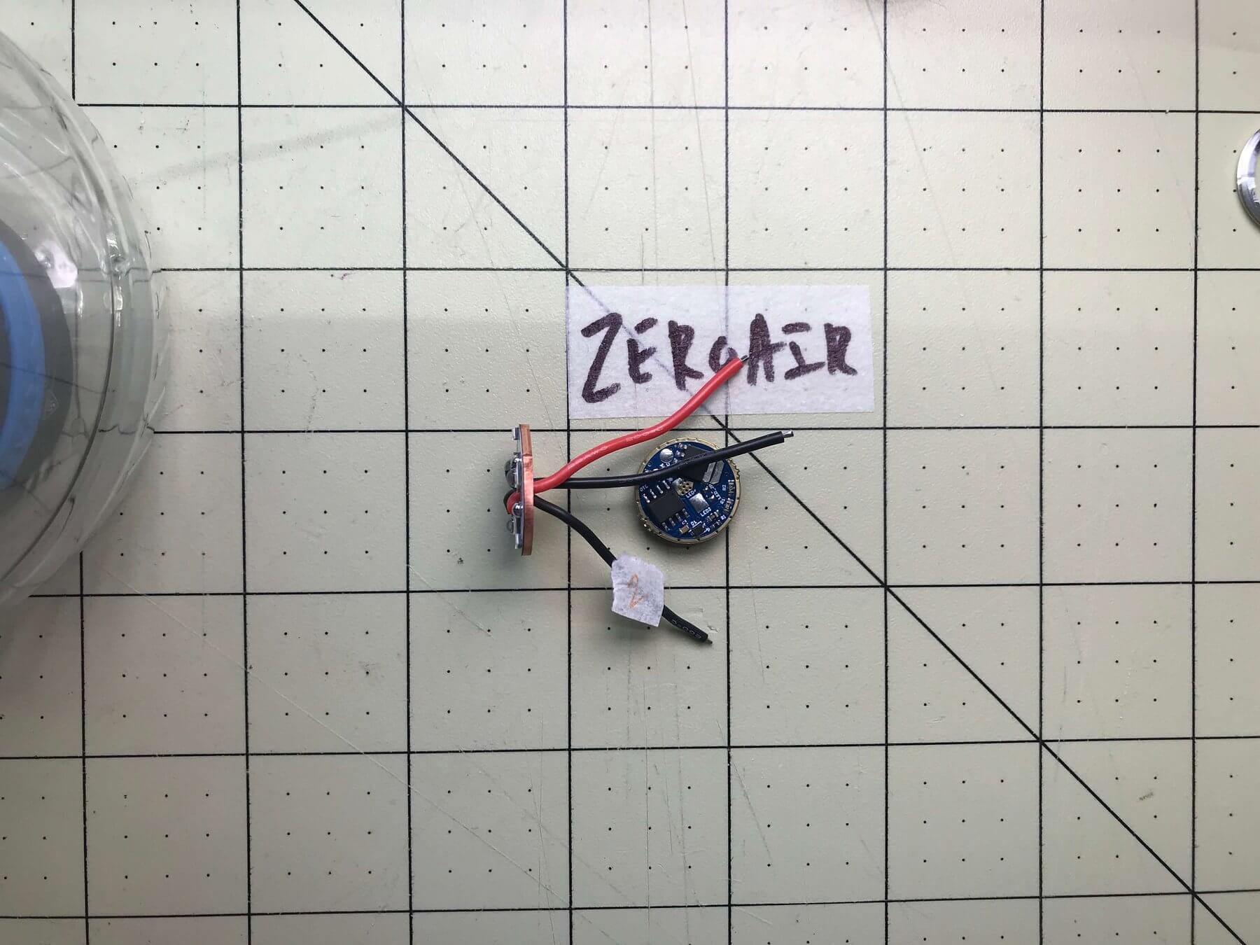
And here’s the business. The part with the wires is the MCPCB with emitters, and the other part which is blue and labeled “CWF” is the driver.
The Other Stuff
You’ll need the usual soldering supplies, which I won’t really cover here. If you weren’t building a MechTorch, you’d also need an optic, a switch, and possibly any number of other things! All things I won’t really cover here.
Regarding the Internals (AKA ‘On The Pill’)
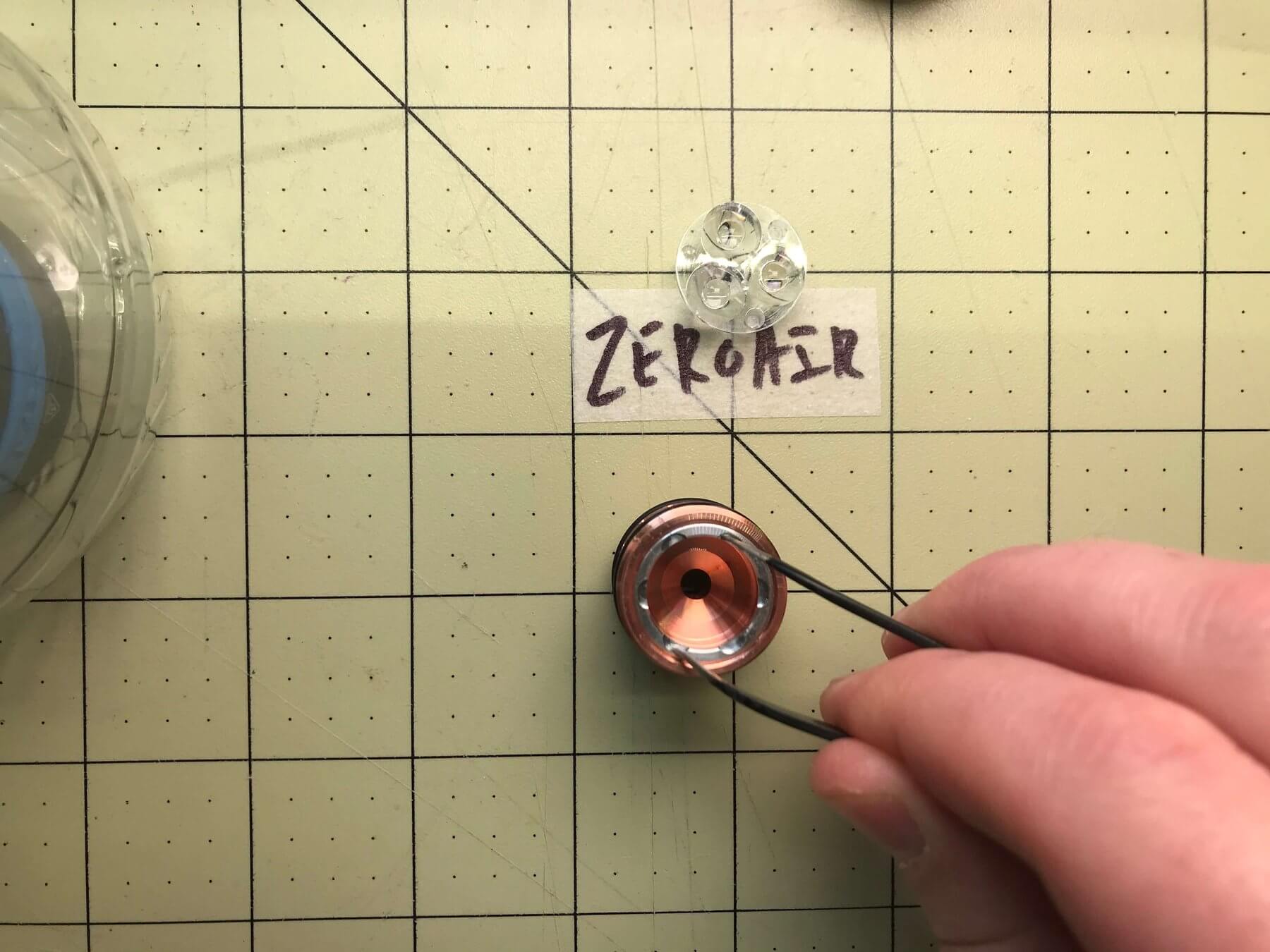
On the MechTorch, the pill disassembles easily by unscrewing. Unscrew the bezel and remove the optic. Unscrew the retaining ring and you gain access to the driver area. That’s really all there is to it on this host.
I used some bent tip tweezers to unscrew this driver retaining ring.
Here I’ve started to size up the parts. Since drivers and MCPCBs are available in different sizes, you’ll need to be sure to buy the right sizes for your build. In this case, as the product page says, you’ll need:
Triple LED board with 19 mm or 20 mm outside diameter
LED Driver Board with 17 mm Outside diameter
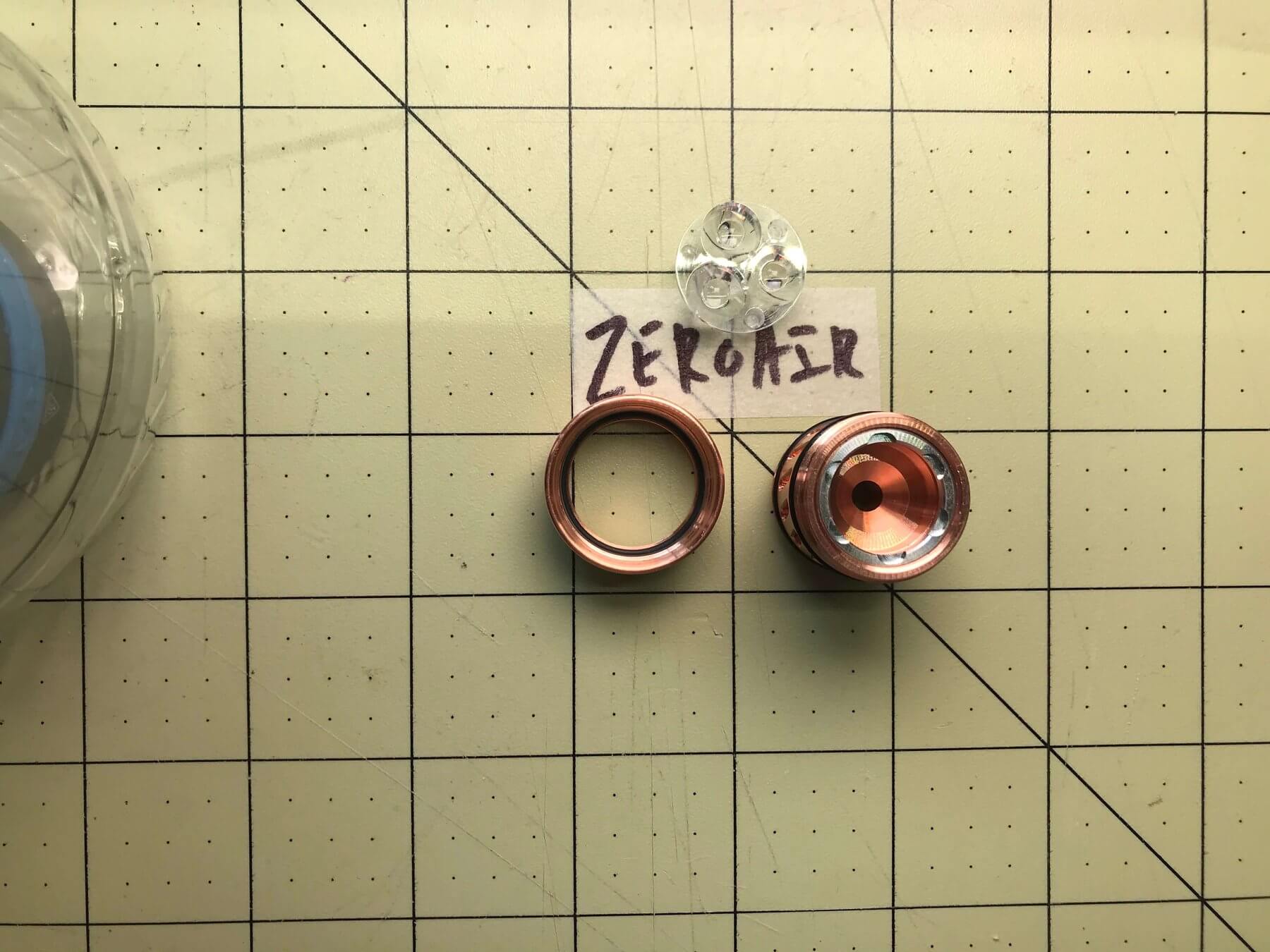
Test Fit
Throw the parts in there dry and see how things line up. No need to go putting metal on metal if things aren’t copacetic. First I make sure the driver is the right size. Also there are some pcb tabs that might need to be filed a bit for a proper fit. In my case no extra cleanup was necessary.
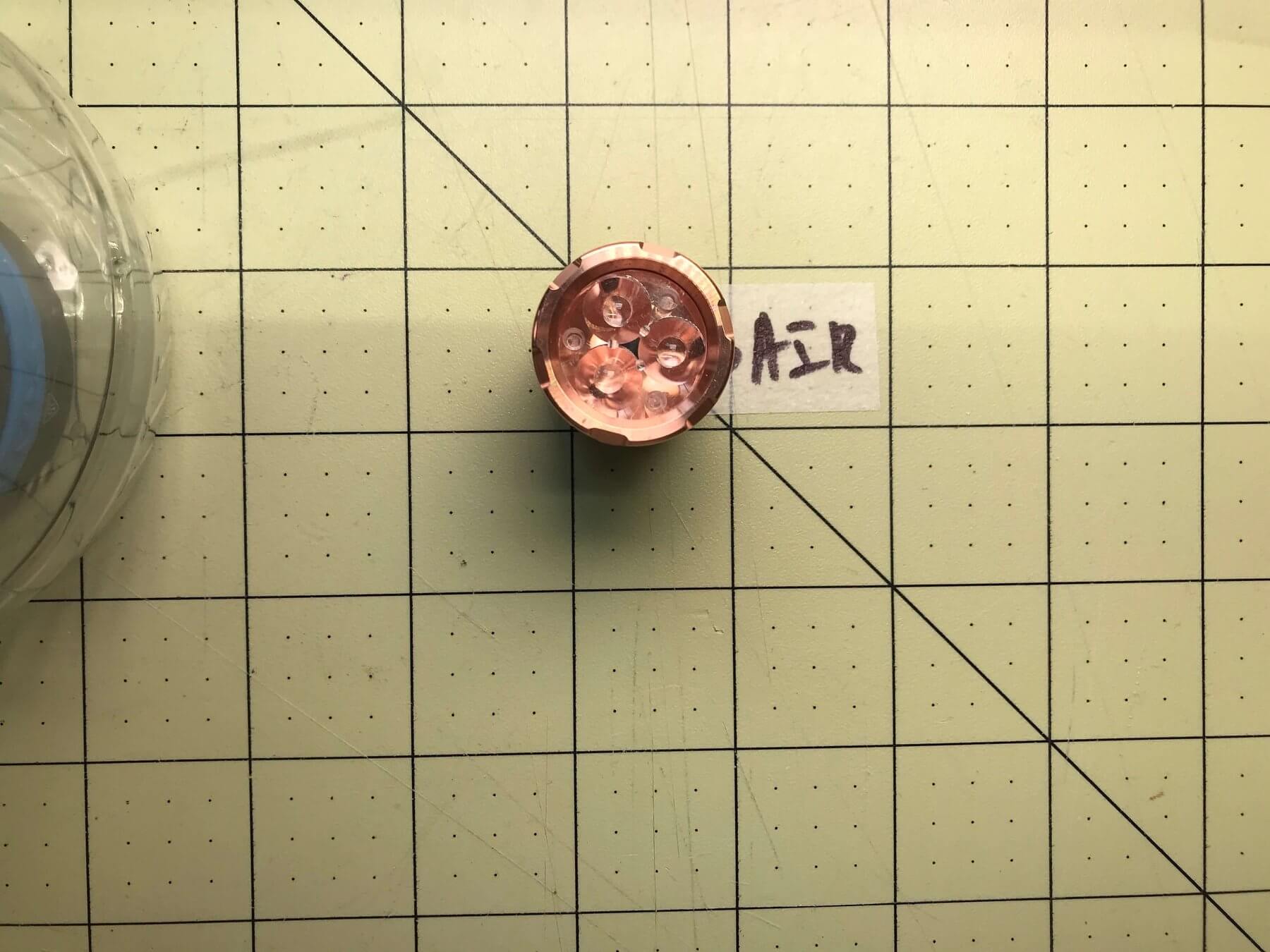
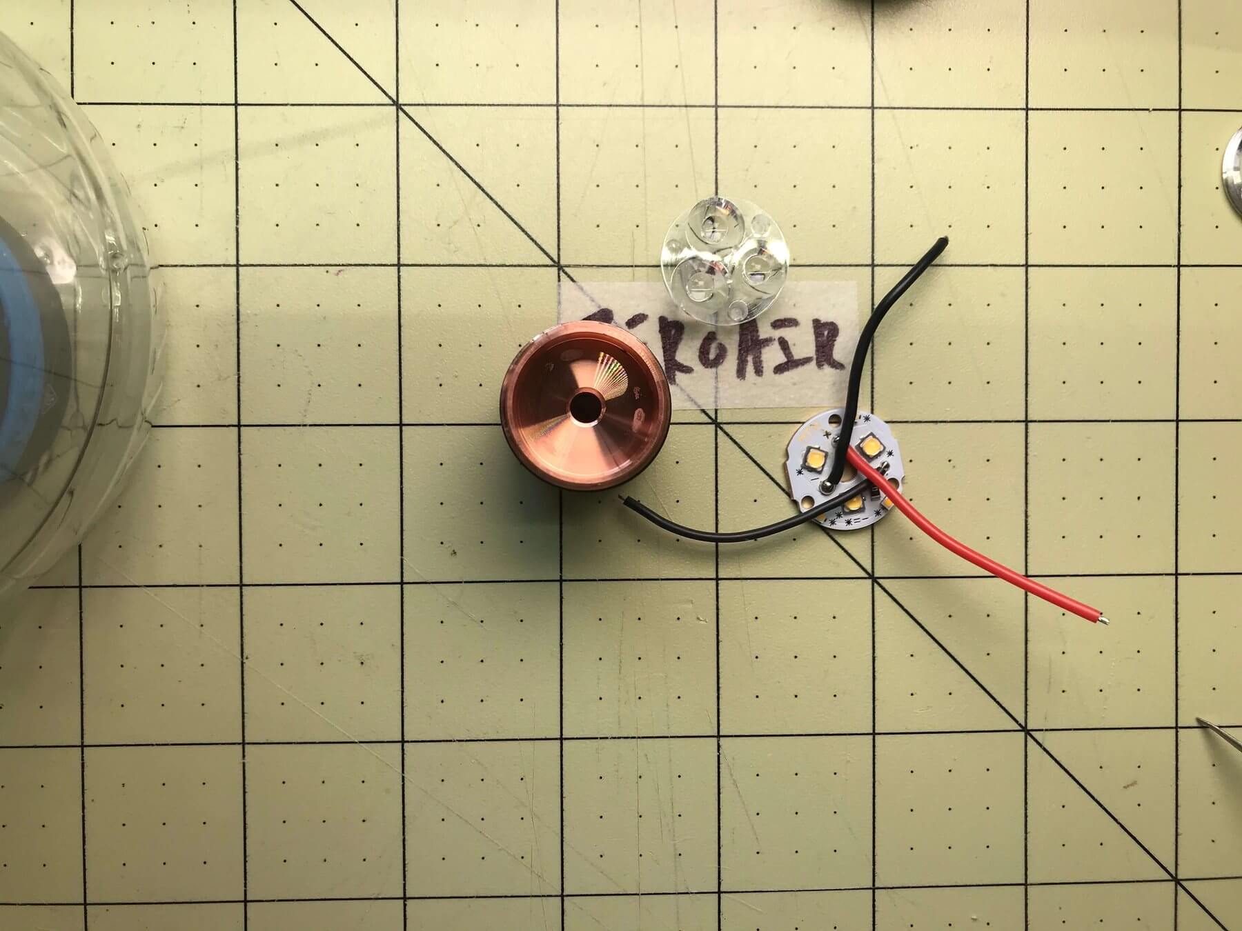
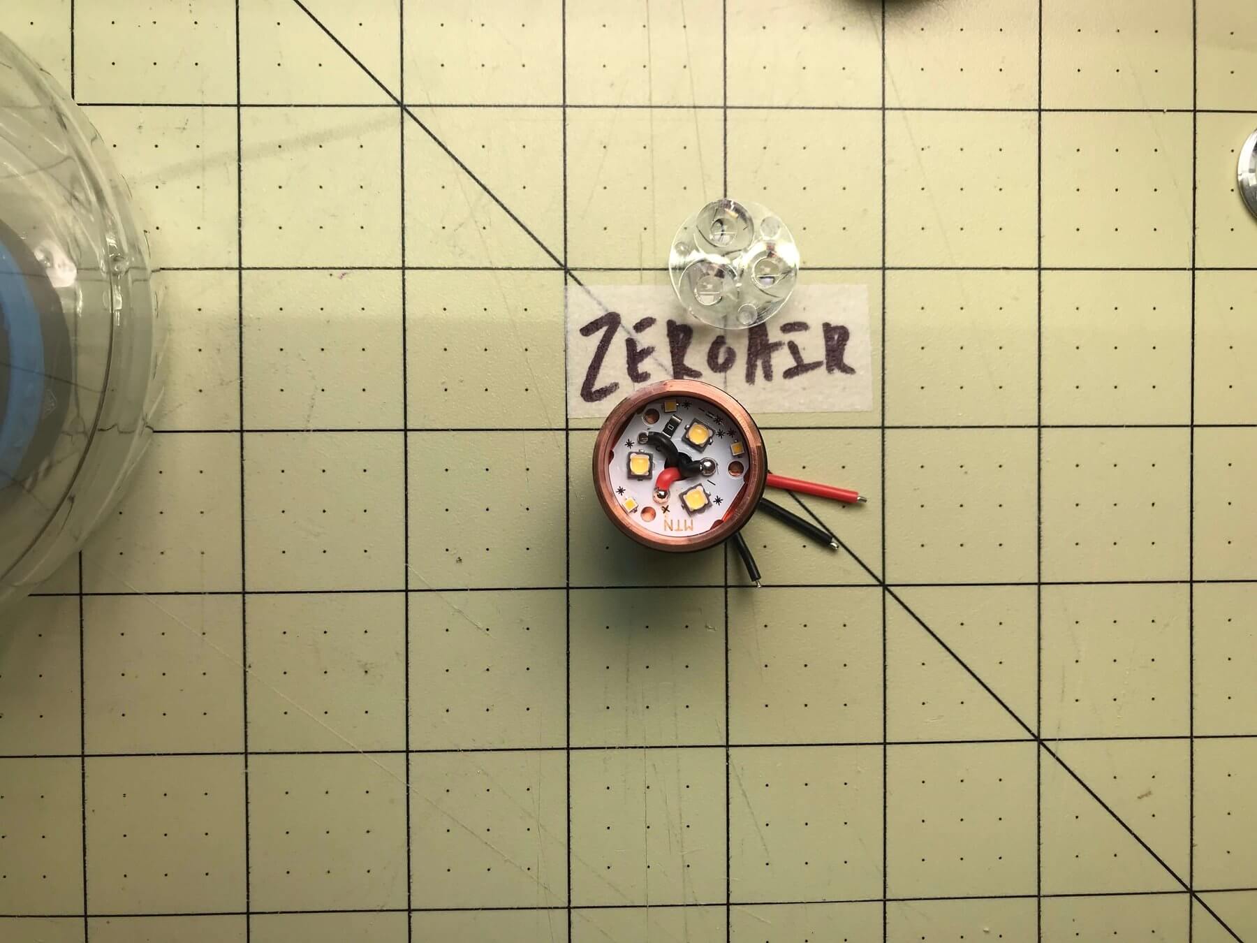
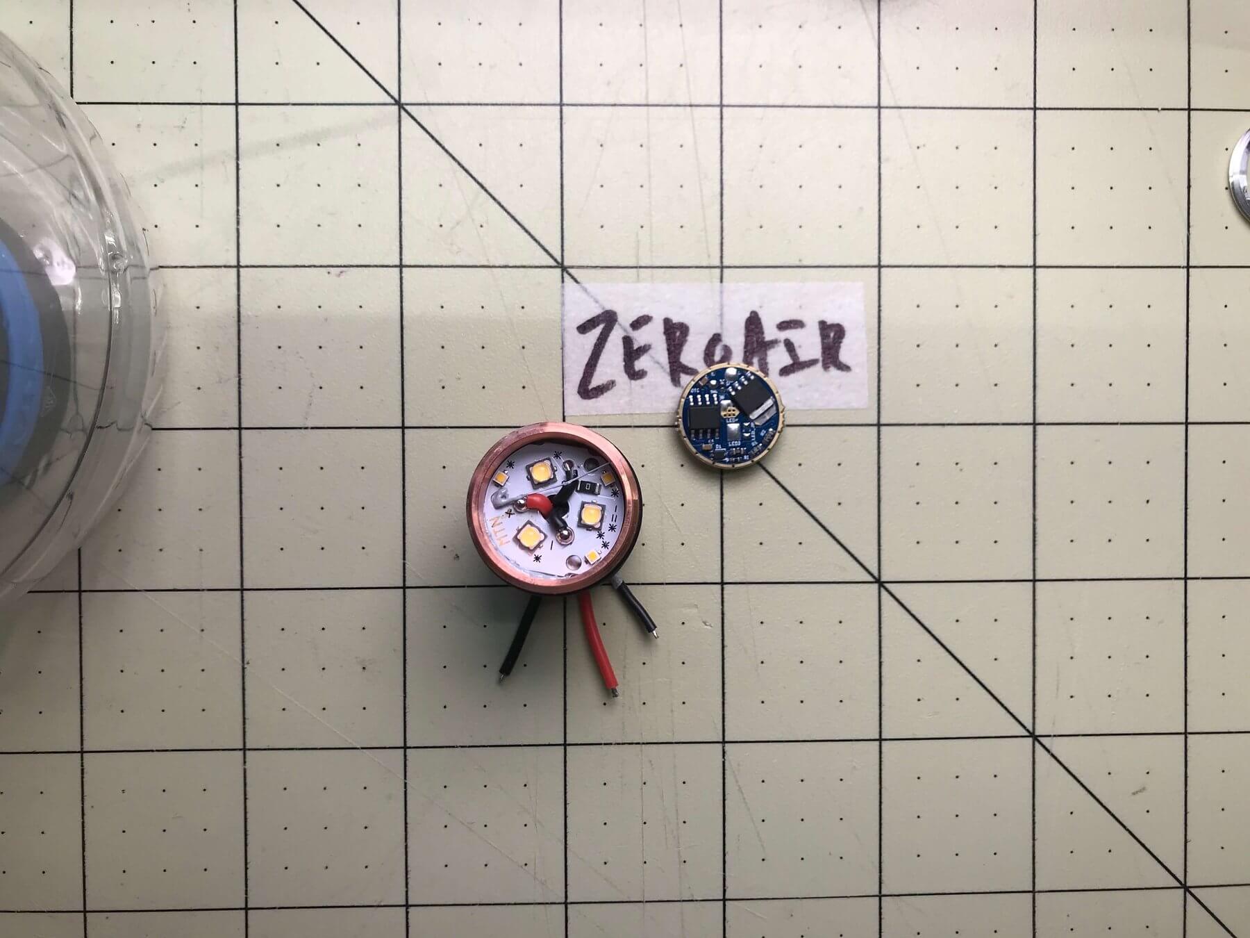
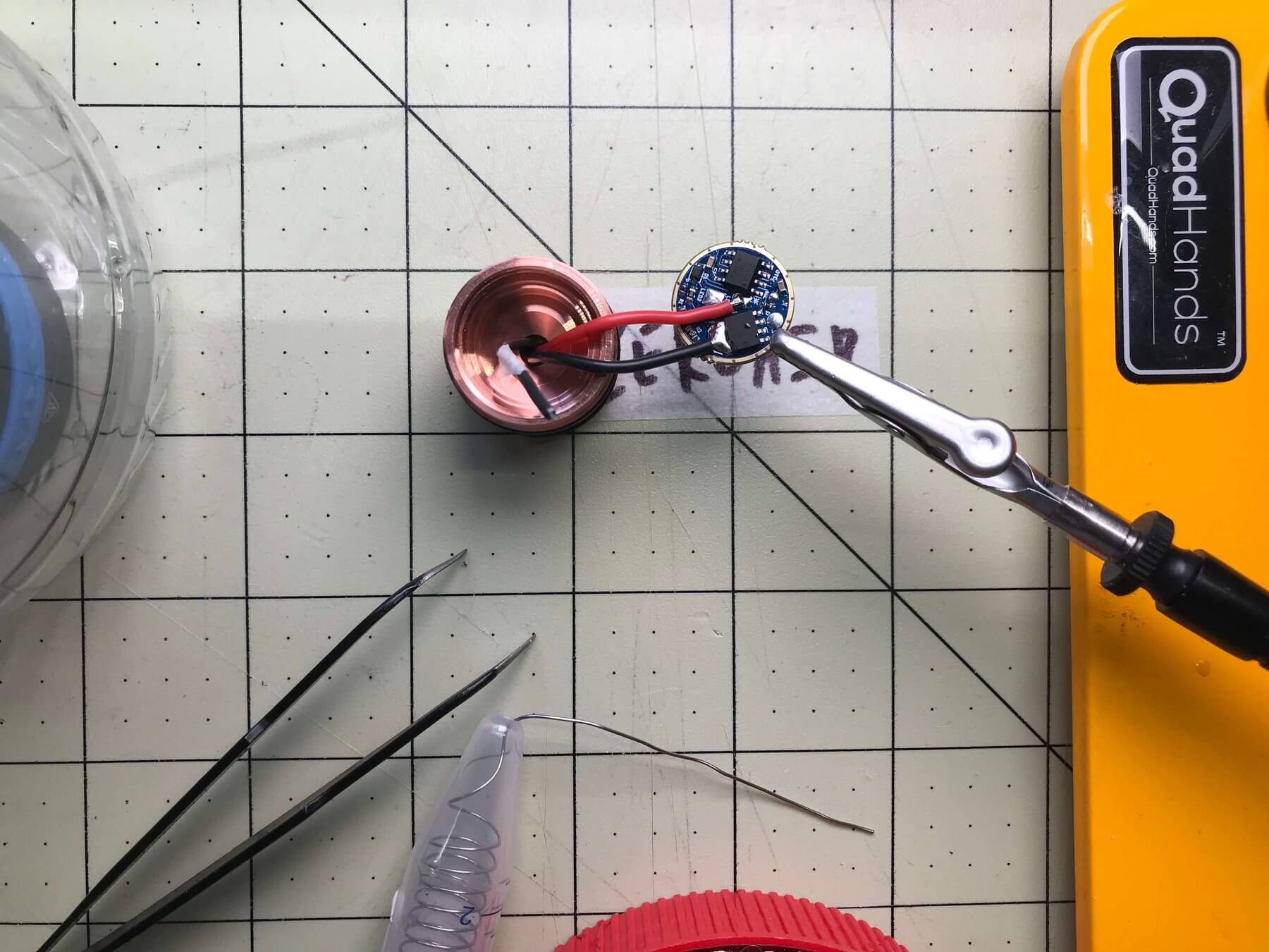
And make sure that the MCPCB with emitters fit. In my case, I needed to put the wires through the hole in the center of the board. The three holes on the edge of the board are not for the wires – those holes are made for the optic to rest in. So put the wires through that hole. Then put the MCPCB into the host, and pull the wires through the hole in the pill.
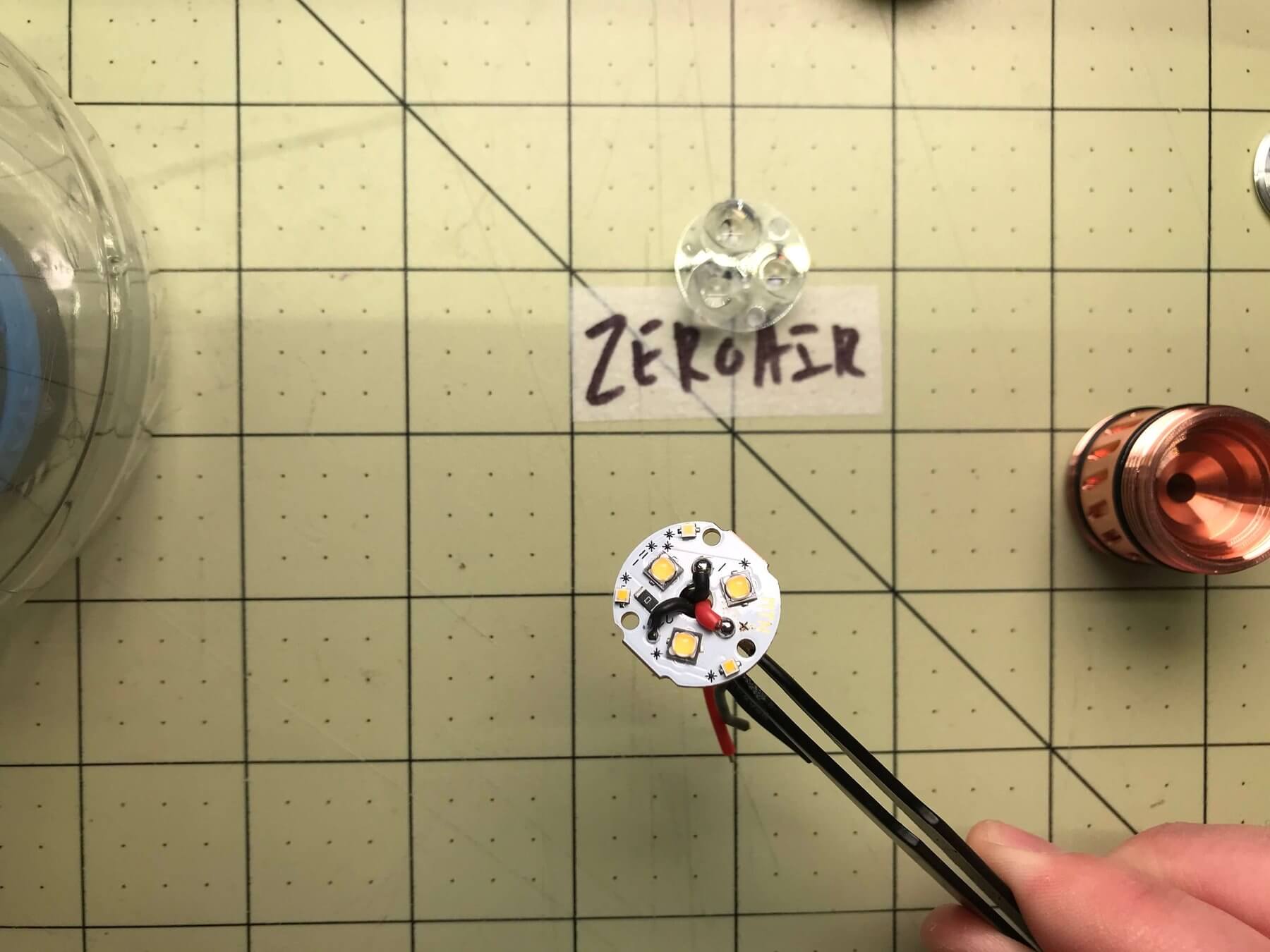
Note something here. Once those wires are pushed through, it’s a little hard to tell which wire matches which. There’s only one red, so that’s easy, but which black is which? They aren’t labeled, and I could probably convince myself that one is smaller so it’s probably the wire for the secondary emitters.
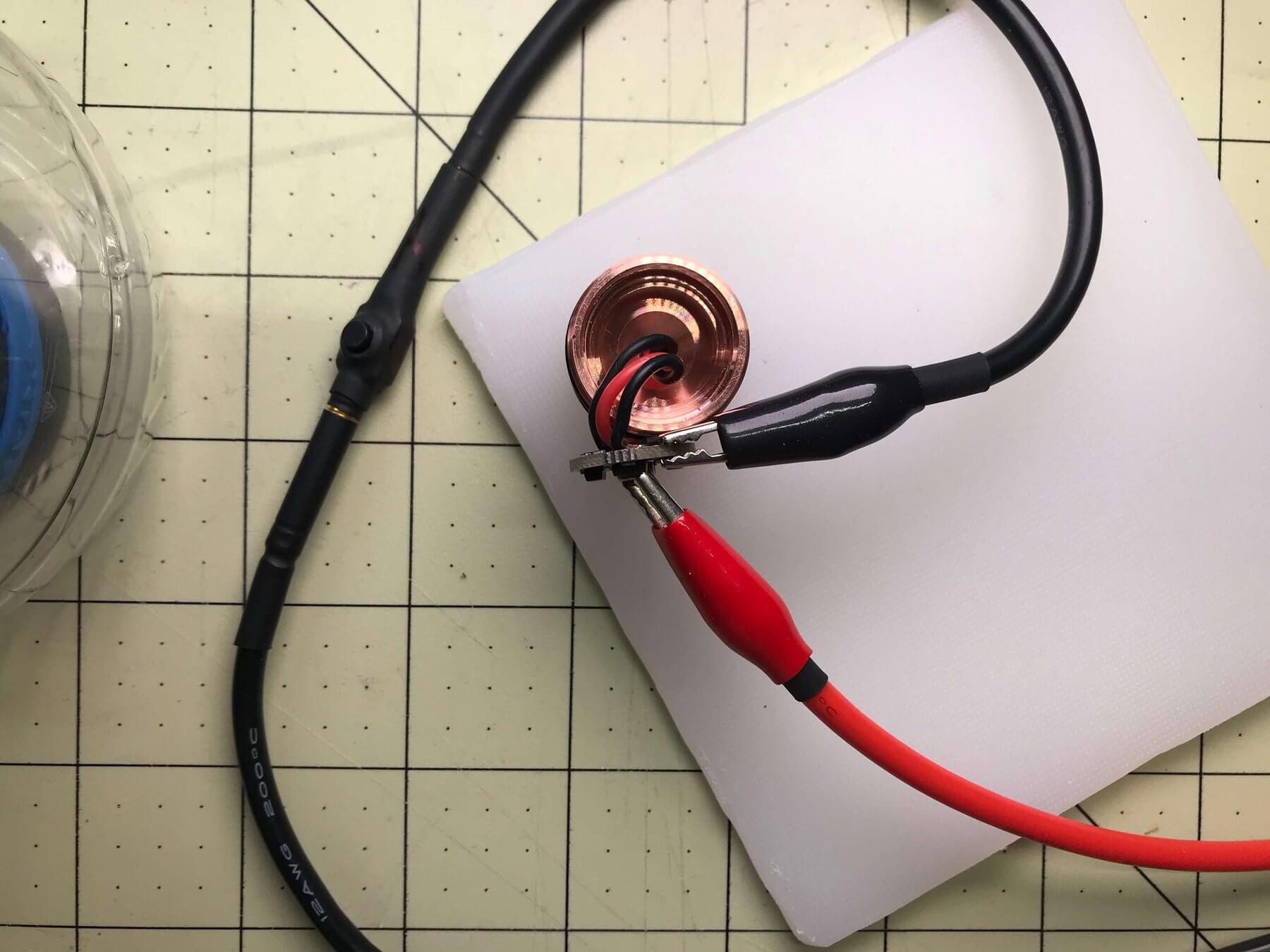
Electrics Test
Why not just test it and label it. A long while ago I built a bench power – you can see that other “How Do I…” post here. I use this thing so much. I love it. You should build one.
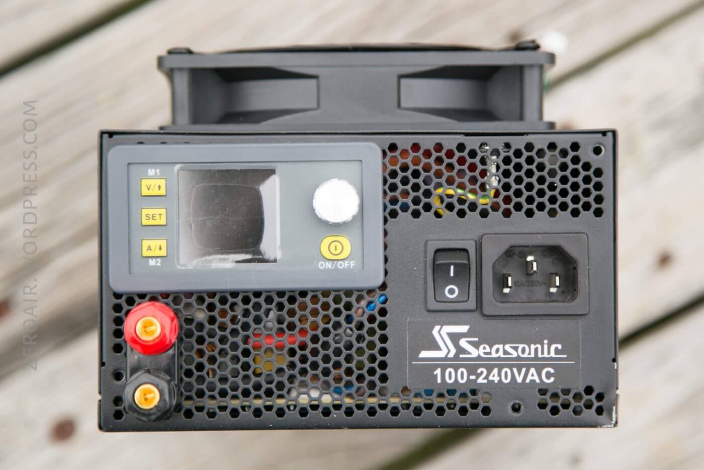
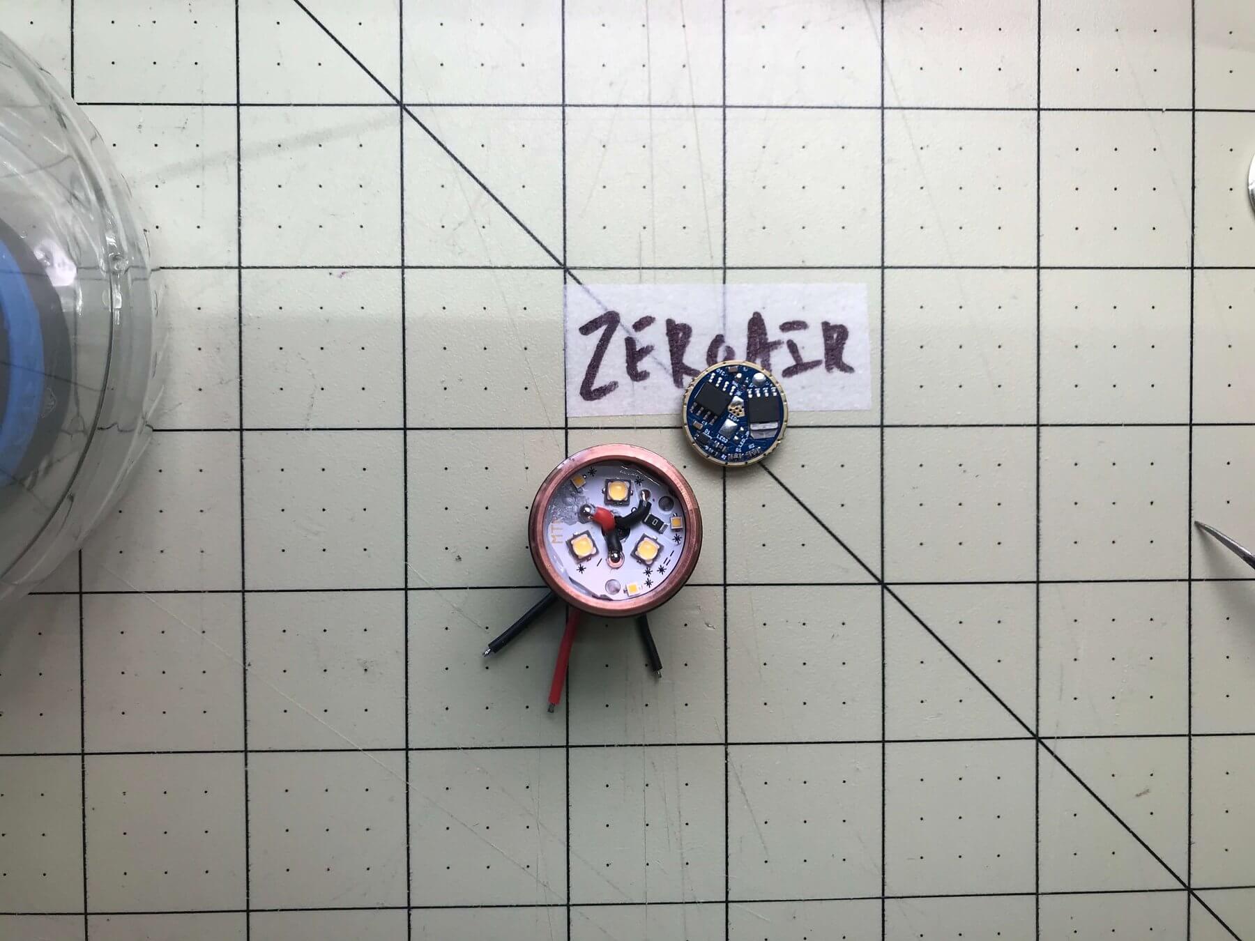
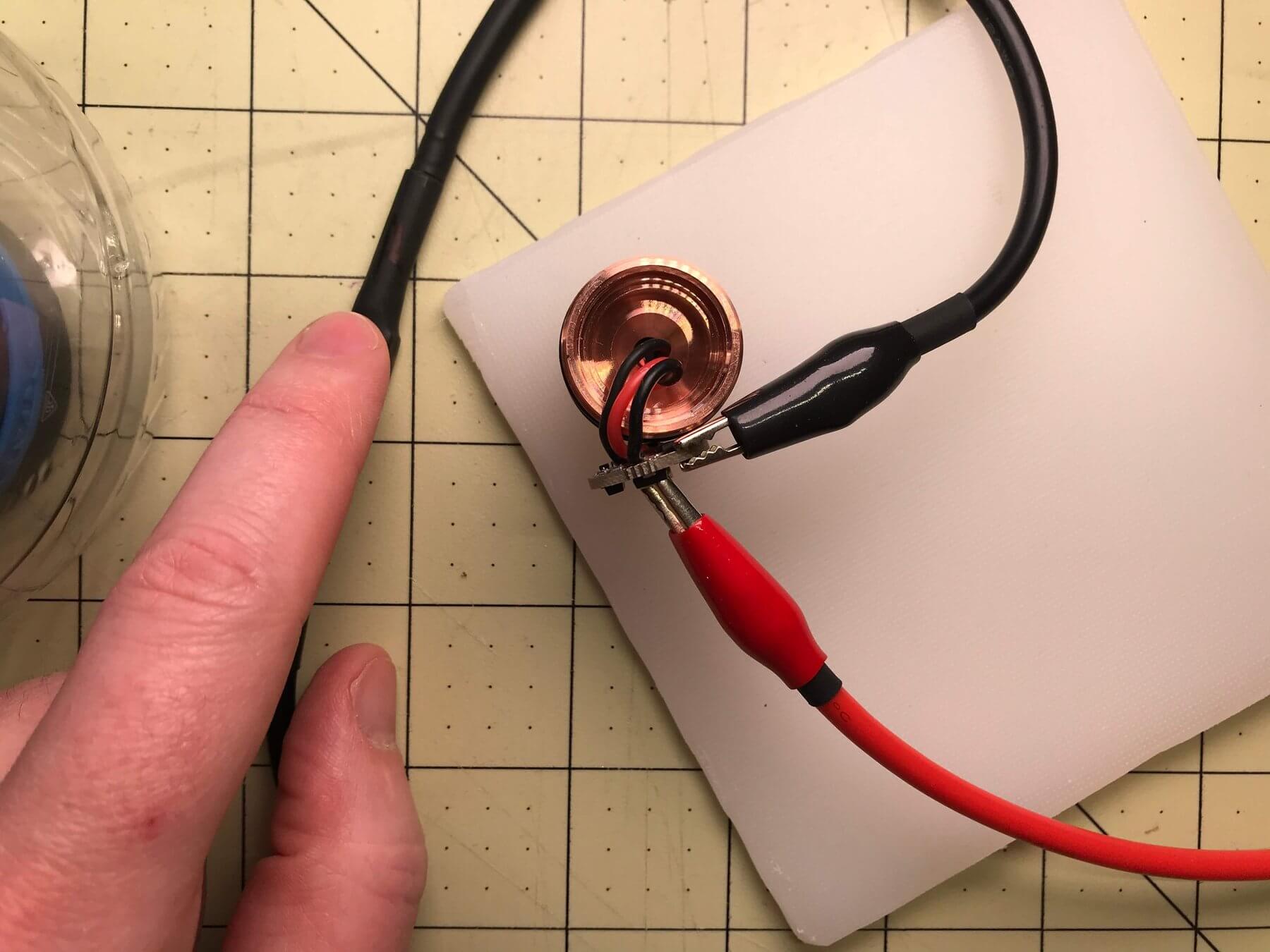
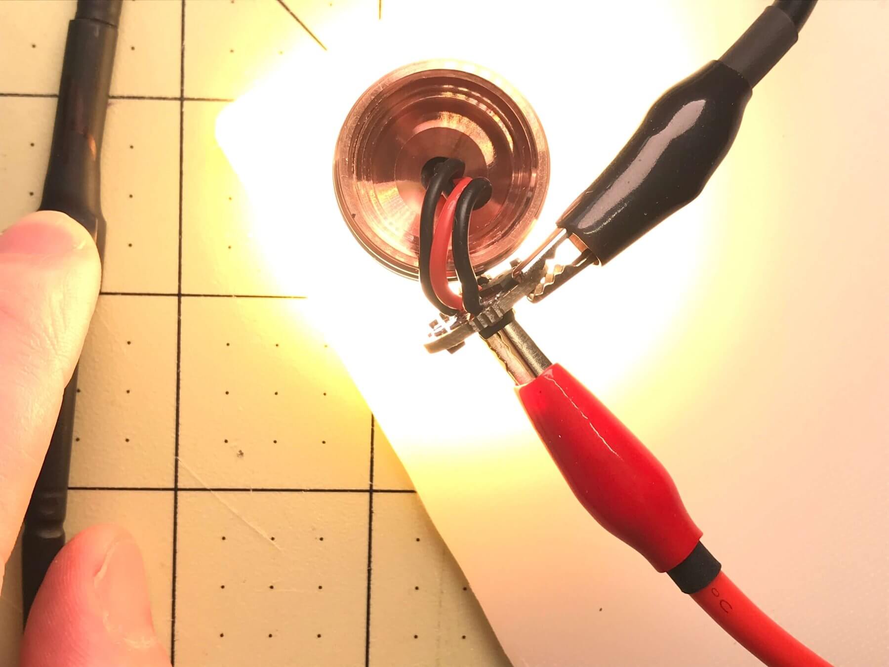
Connect the bench power properly to red, turn it on at 4.2V with very minimal current max (I think I set it to 0.01A or something very low). And touch the black wires to see which ground relates to which emitters. They share a positive (red) but have individual grounds. I put a bit of tape on the amber ground, and move on to step next.
I didn’t do it, but if you have a decent digital multimeter, you should be able to test this with the diode setting. You might even check it with the beep setting of continuity. Wish I’d thought to test that! But build a bench power anyway. 😀
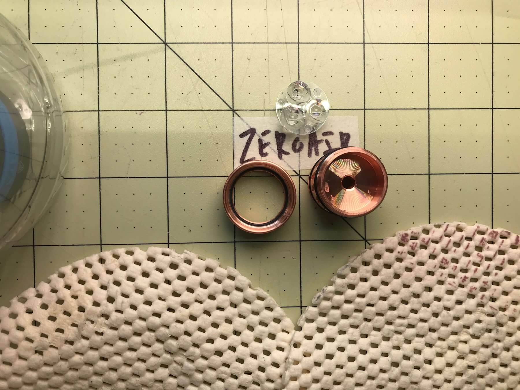
Thermal Paste
The next step is to put thermal paste under the MCPCB, and push the wires through. Donnnnnnn’t use as much as I did. It takes a very small amount. And it’s sticky and gooey stuff! Just use a very small bit, maybe dab it in 3 areas so you can twist the board a bit, and get good coverage. Thermal paste is what will help transfer heat from the MCPCB to the pill.
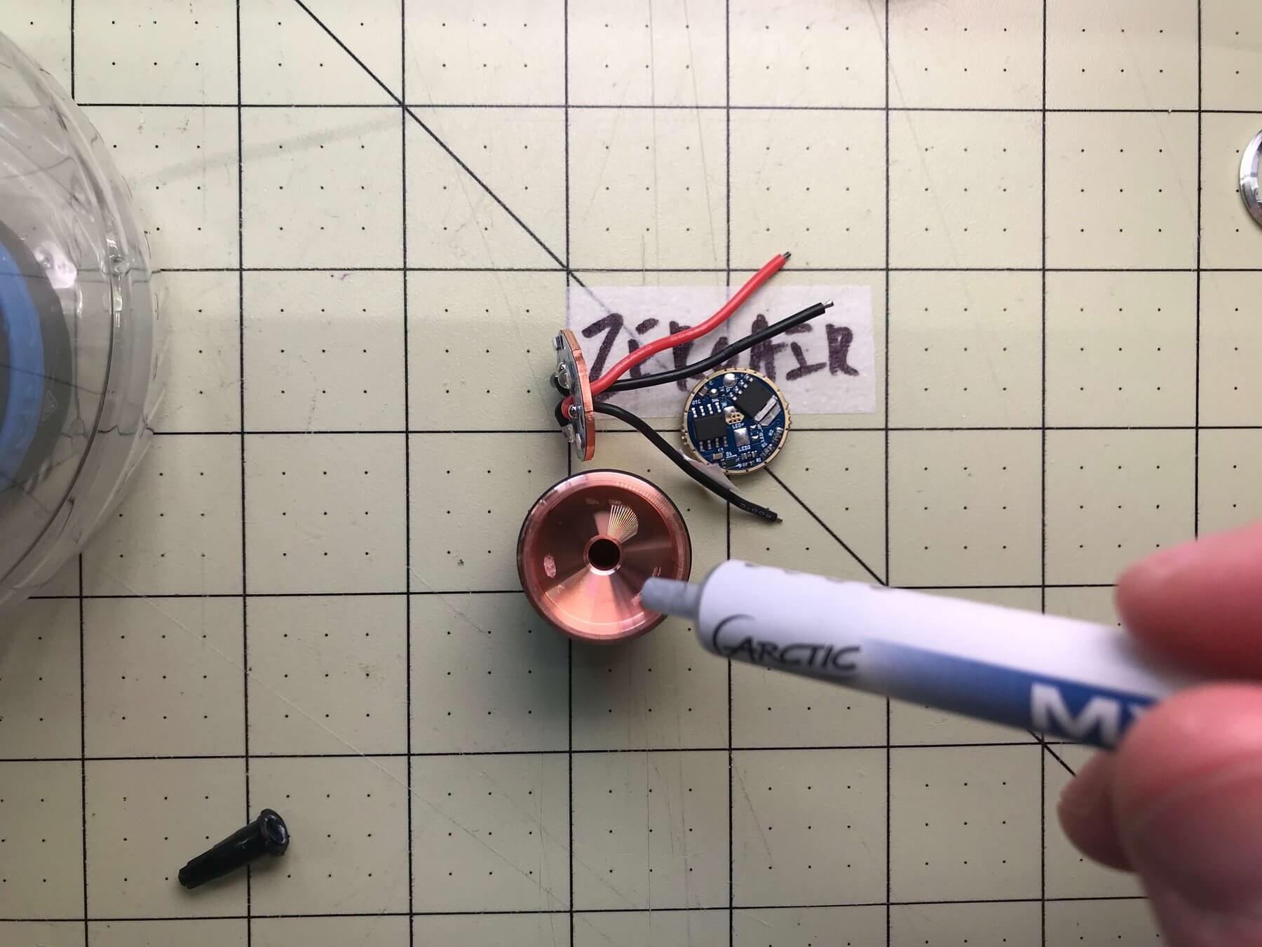
Again, I used too much. I didn’t even use that much. Ideally, you want to use just enough to fully cover the board with no air. The goal isn’t a layer of paste, it’s no air gaps between the MCPCB and pill!
I’ll tell you about the driver who lives inside my head
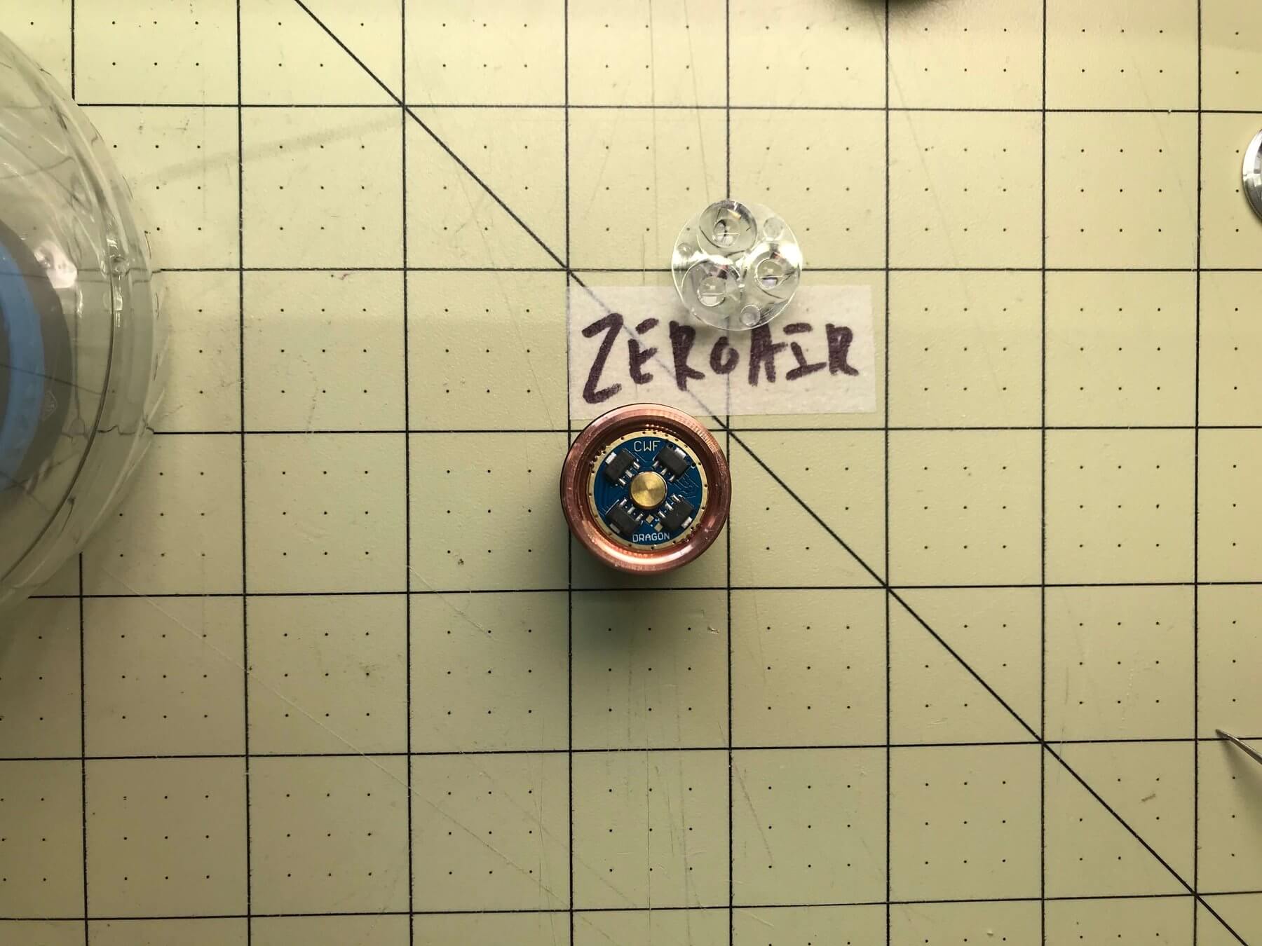
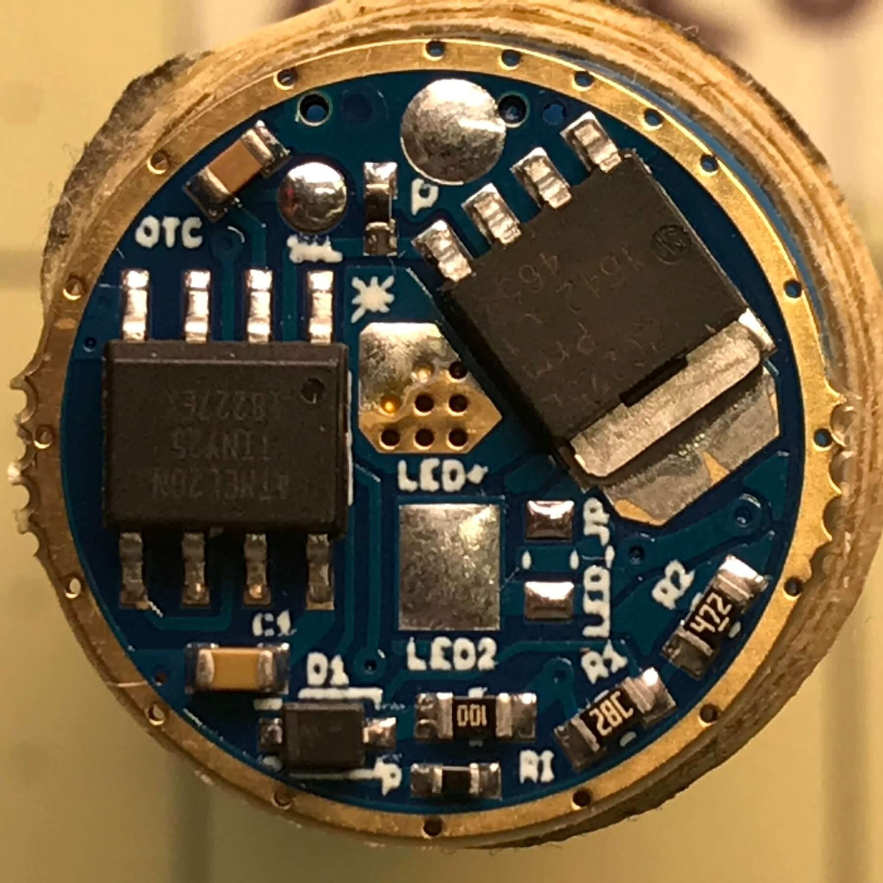
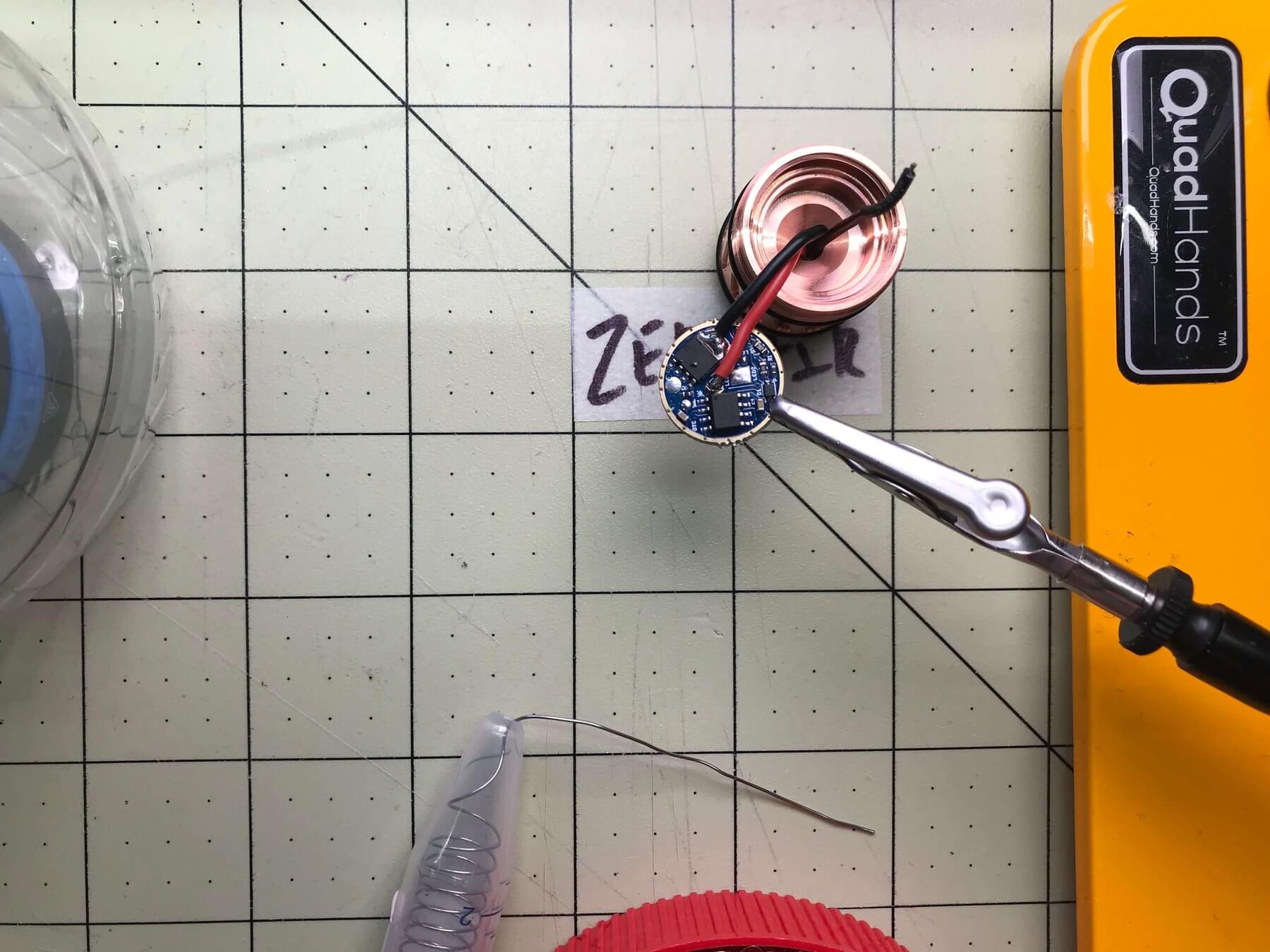
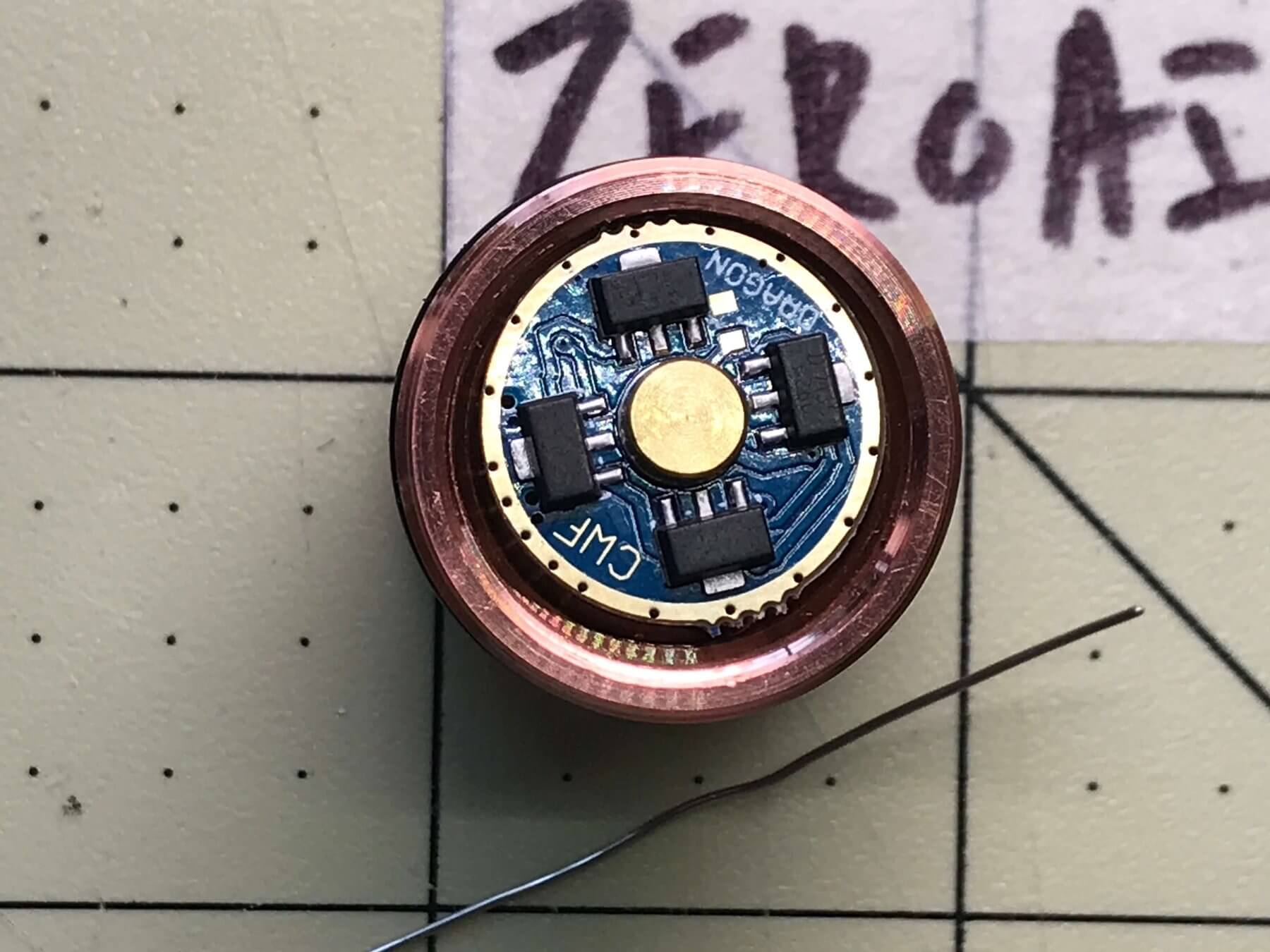
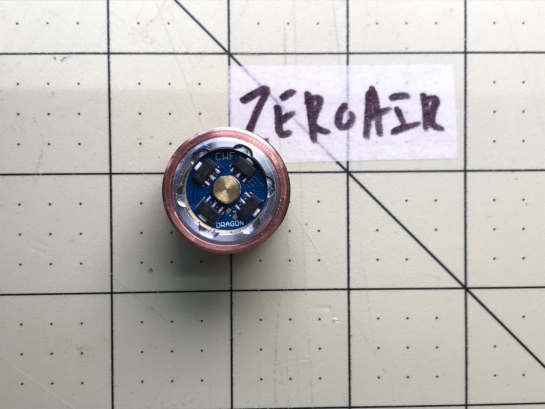
I picked a CWF Dragon driver for this build. Here’s a close-up. As I said above, it has three leads to connect. I’ll have to solder those leads somewhere on this board.
The board is sort of labeled. You can clearly see “LED+” almost dead center. This is for the pad where the holes are. But aside from that: ¯\_(ツ)_/¯ (best wishes). I struggled on the CWF website to see where went what, and finally had to ask the maker. I got a reply but basically ended up having to sort it out myself. (That’s one reason I am writing this!)
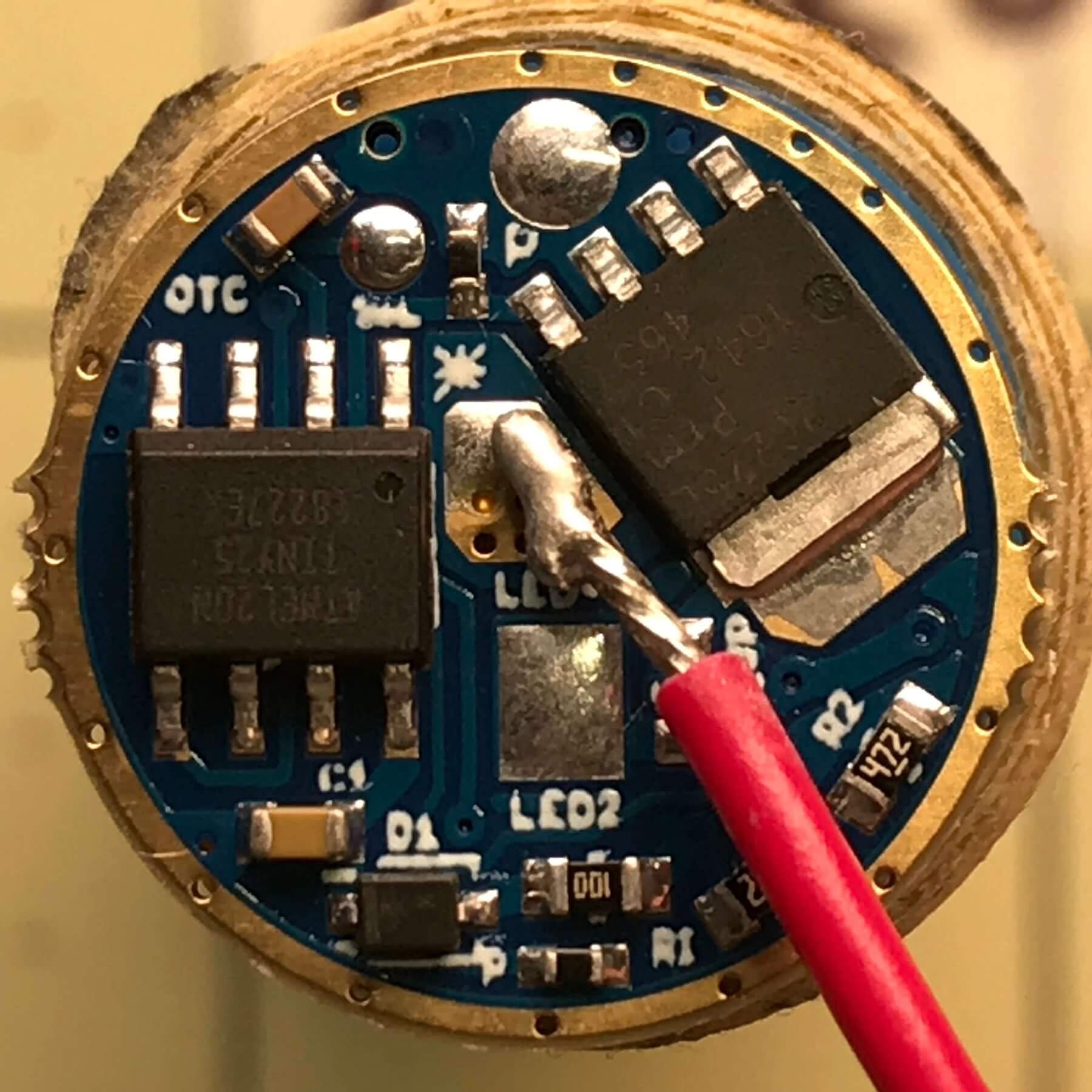
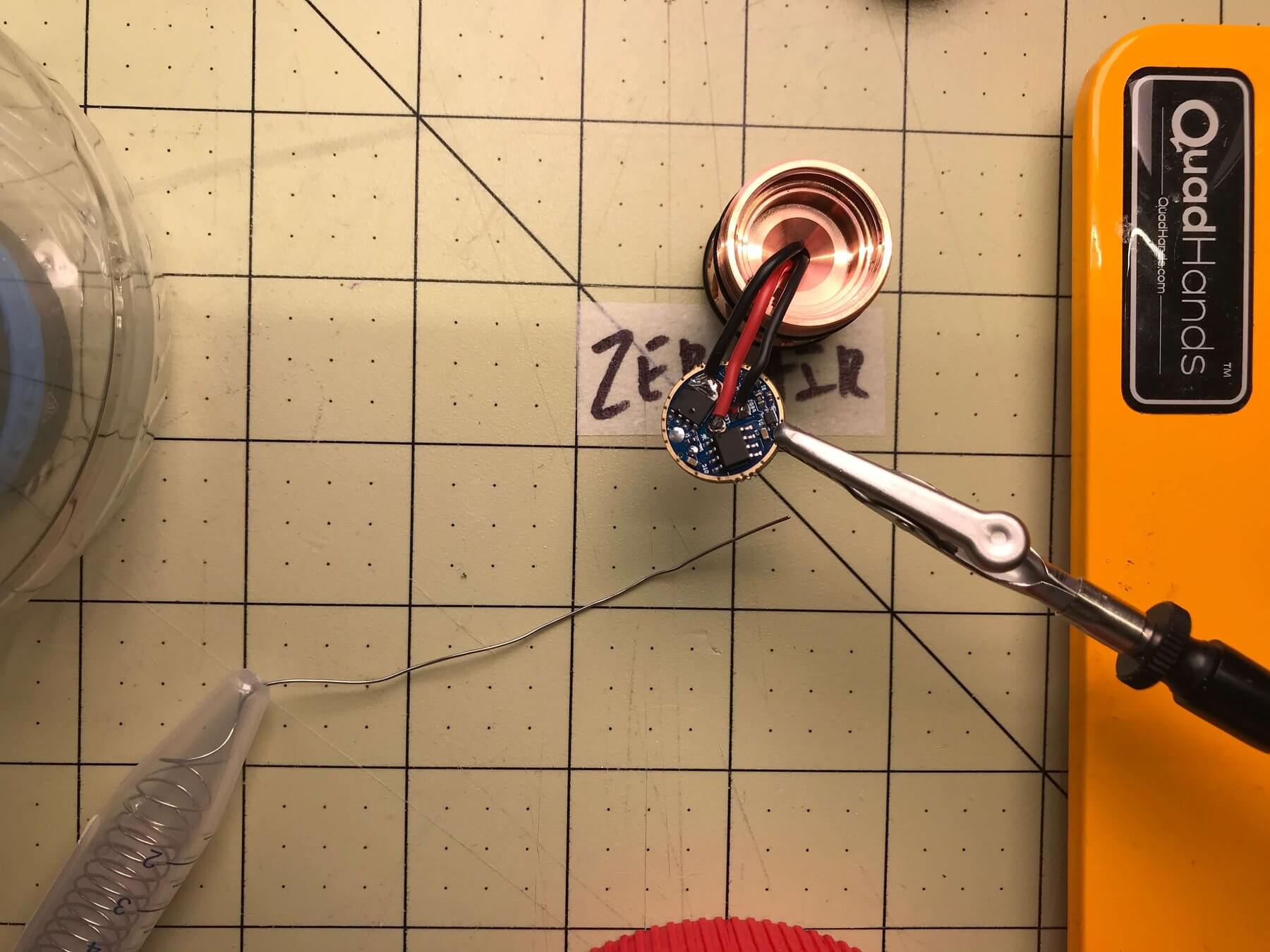
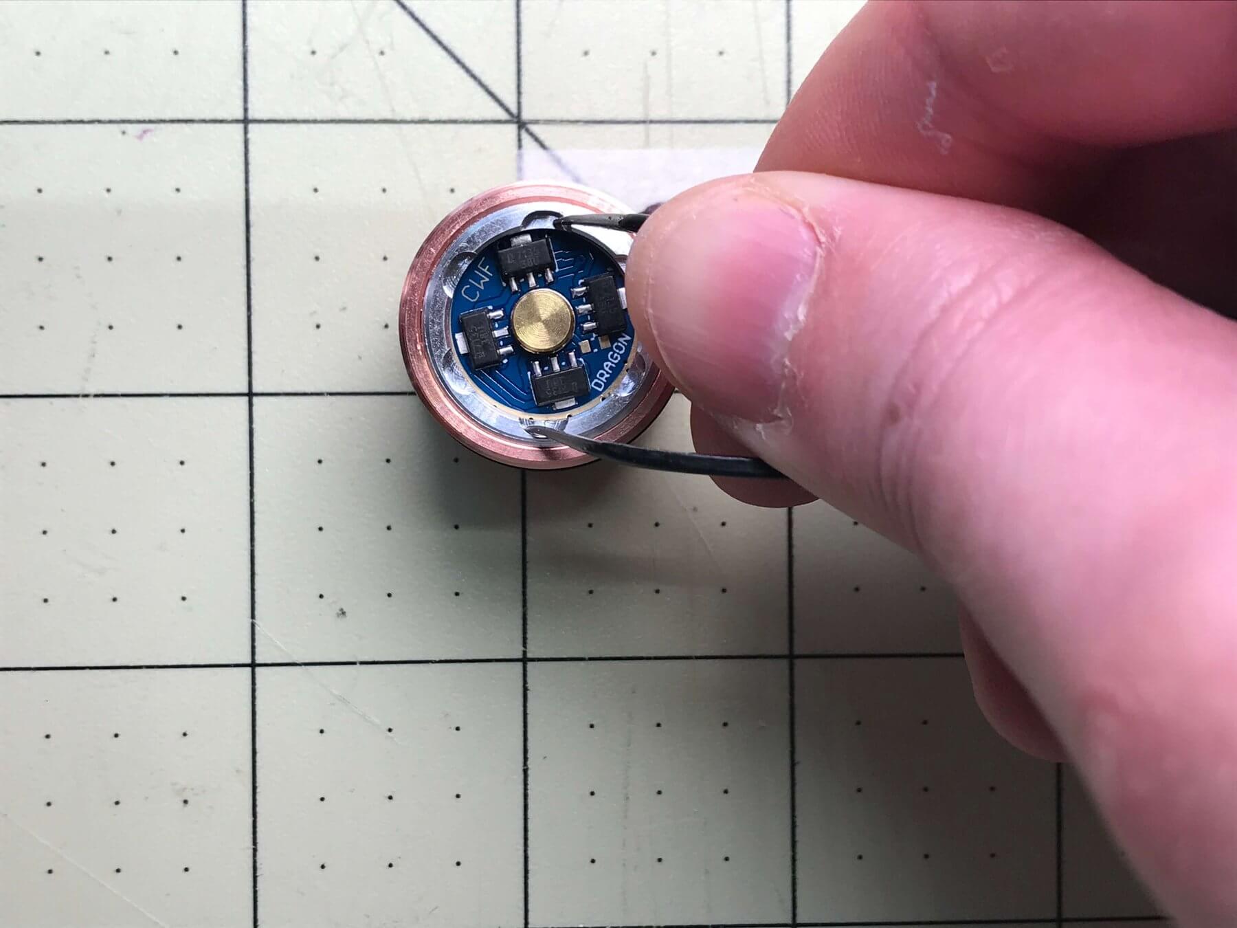
First, red does go to the LED+ marked on the board. (See below I’m holding the red to the right pad). Also, you can see on this lead that the wire tips come pre-soldered, which is a nice touch. All 3 are like this.
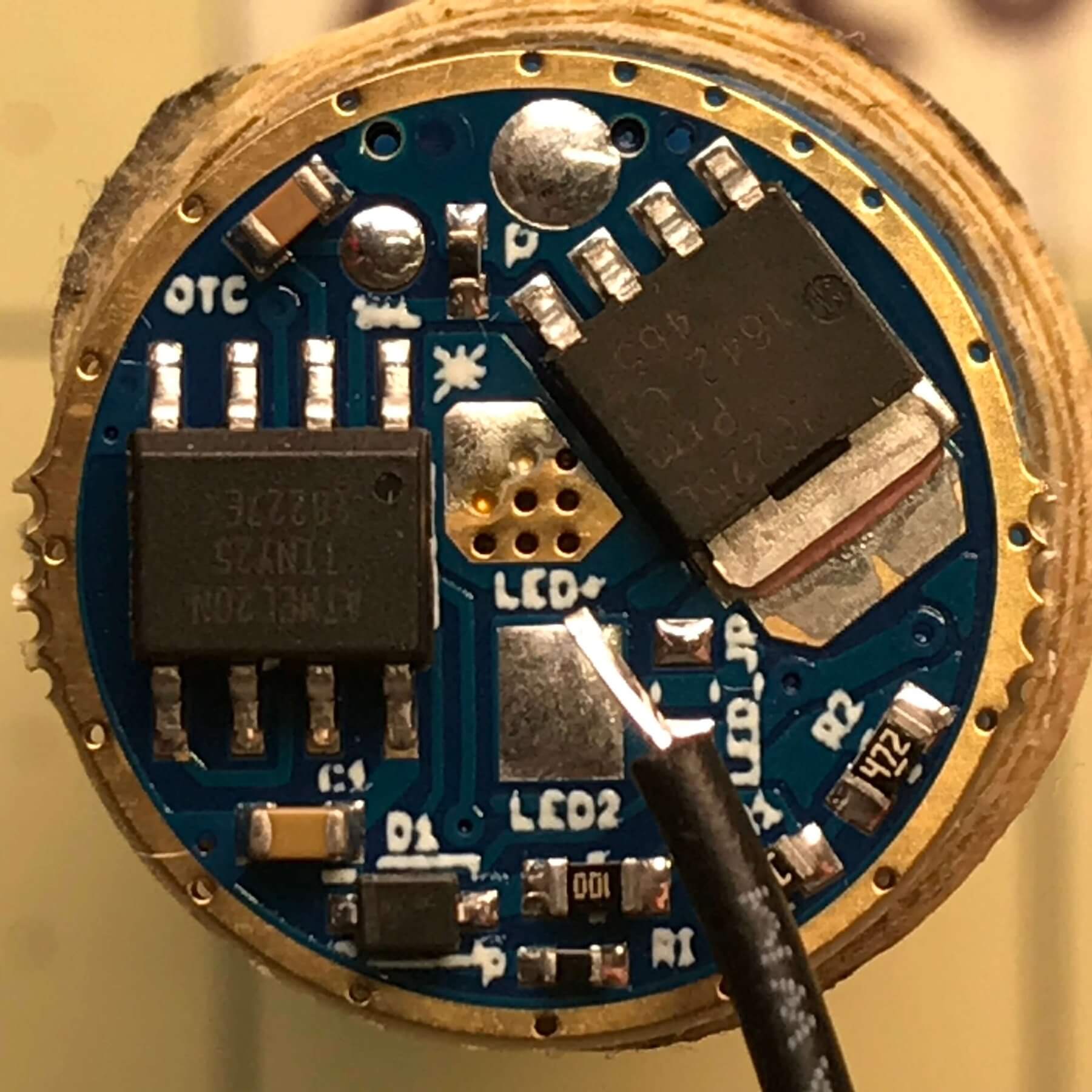
Next, the ground for the secondary emitters goes to the “LED 2” pad, which I’ve indicated below.
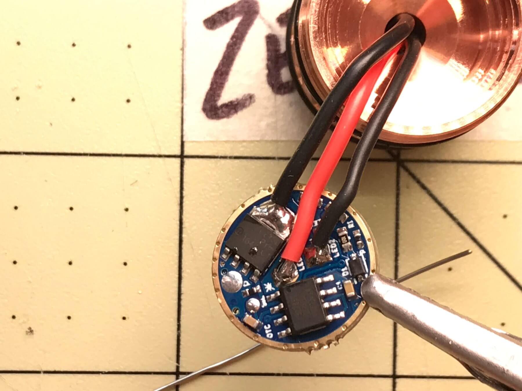
But there’s not a third pad for the ground main emitters? There is but not like the other 2 – that wire connects to a large pad on what I think is the FET.
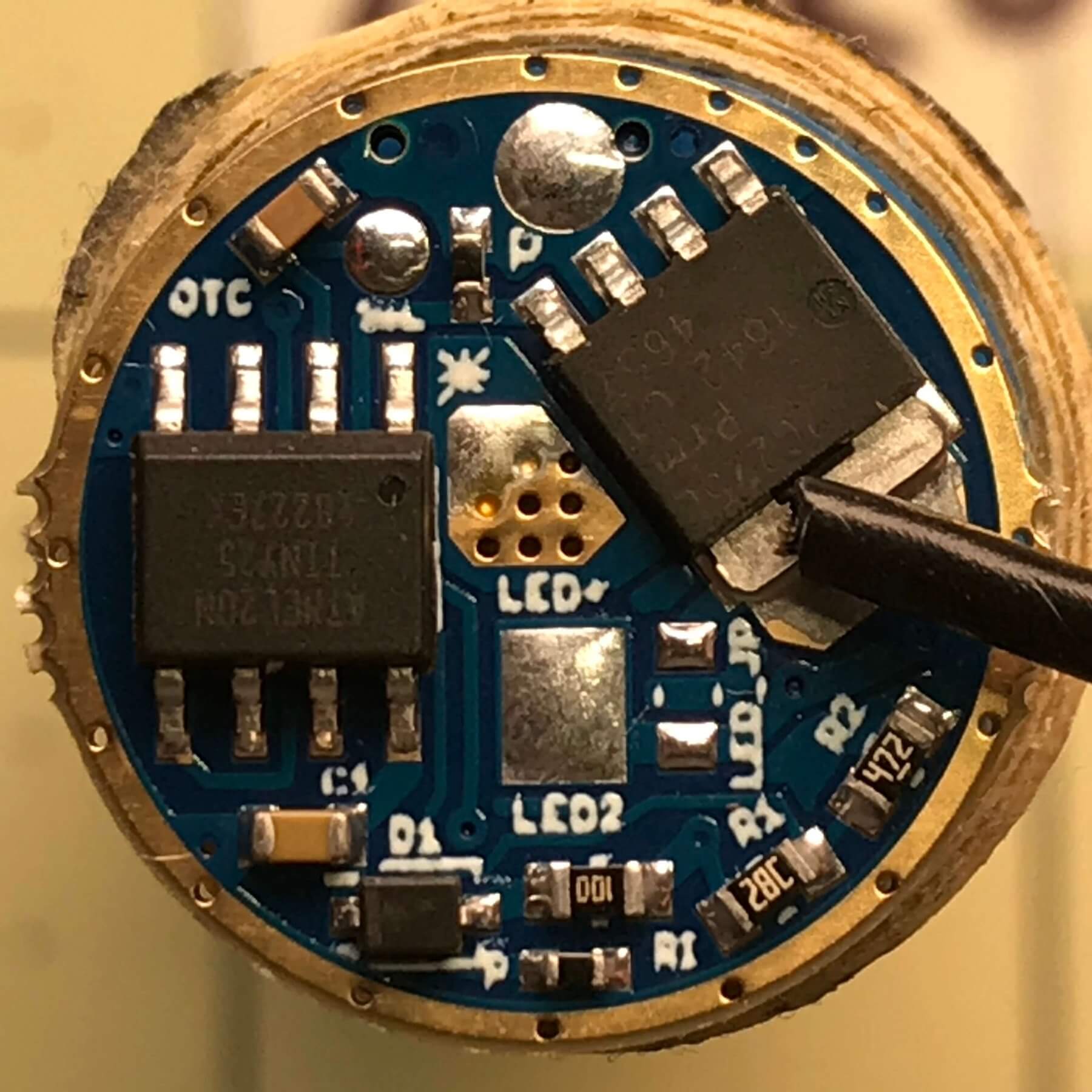
Also note that the wires in my case were different sizes. This isn’t mentioned as far as I can see on the documentation of the CWF page. It’s useful information for certain. Indeed the entire text regarding the MCPCB is as follows:
Complete 20mm MCPCB with your choice of primary leds, amber secondary leds and presoldered wires.
The larger of the ground wires is ground for the main emitters. The smaller is ground for the secondaries. Now you know.
Helpful Tools, pt. 1
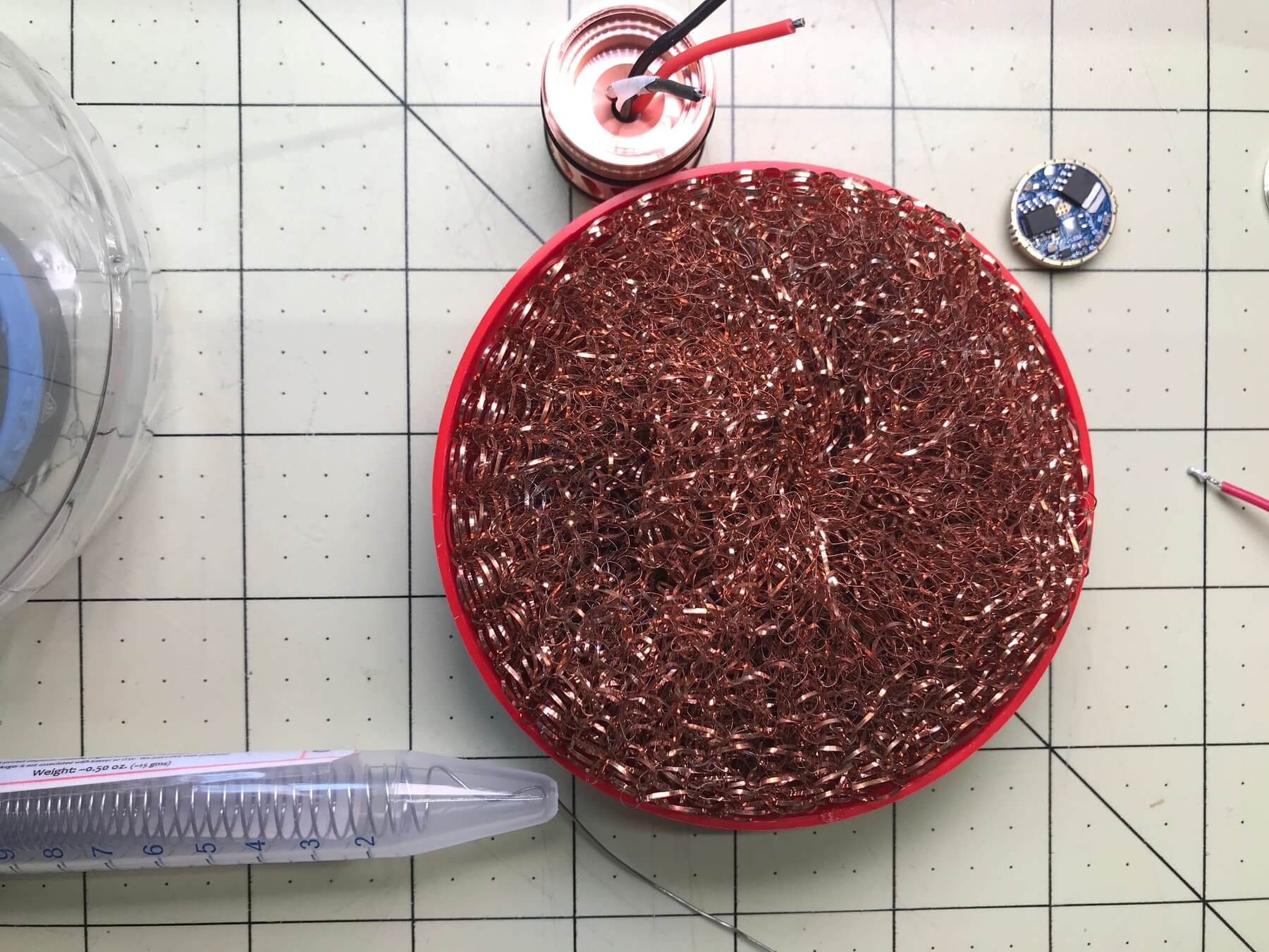
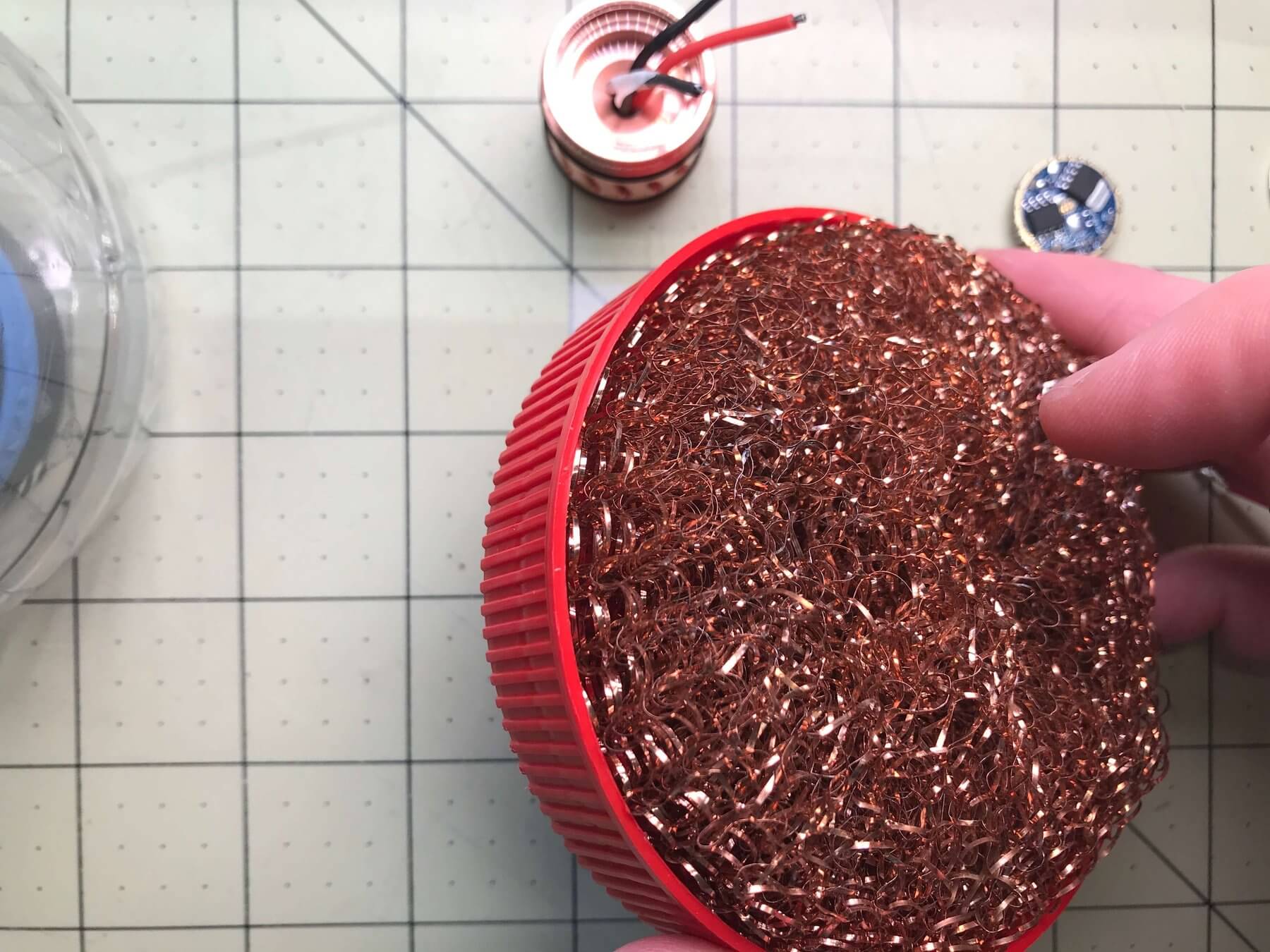
Long ago before I even started soldering, someone told me to use one of those kitchen-use copper scouring pads to clean the tip of my soldering iron. I’ll second that notion, and add to it that those things fit perfectly in large peanut butter container tops. So now I can clean my tip, and the waste falls into the top where it can stay until [who cares when it’s contained].
Can I get, can I get a connection?
Now it’s time to actually connect the MCPCB electrically to the driver. I’ve covered what wires go where, but actually making that happen requires a bit of soldering iron gymnastics. That’s because the leads from the MCPCB are short, and need to be short since in the end they get stuffed into the small area between the driver and MCPCB. Fortunately, the MechTorch has a bit of space. In any case, I went with these leads as provided, which seem to be average length.
I added a bit of solder to the pads first, and the leads were pre-soldered.
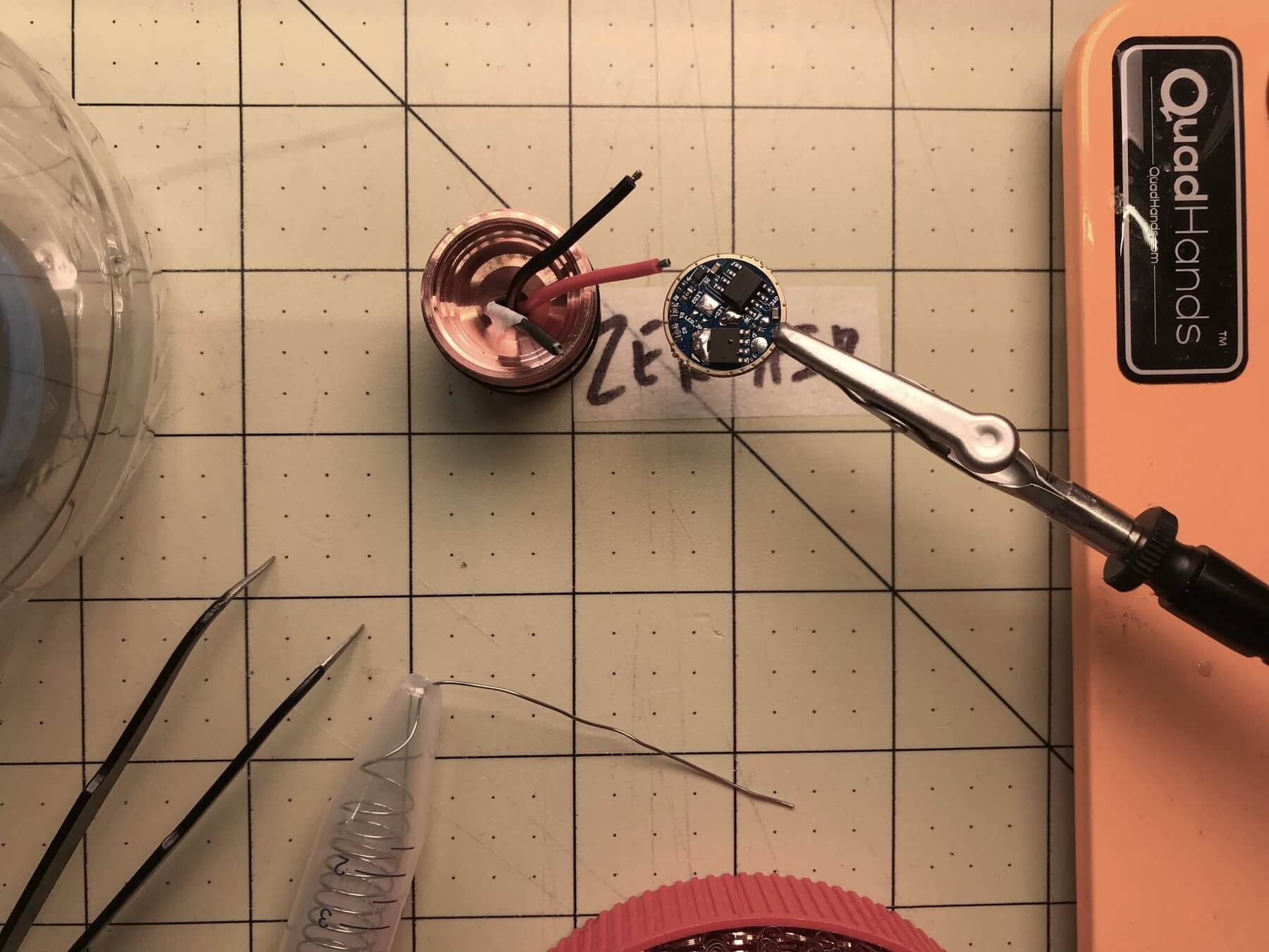
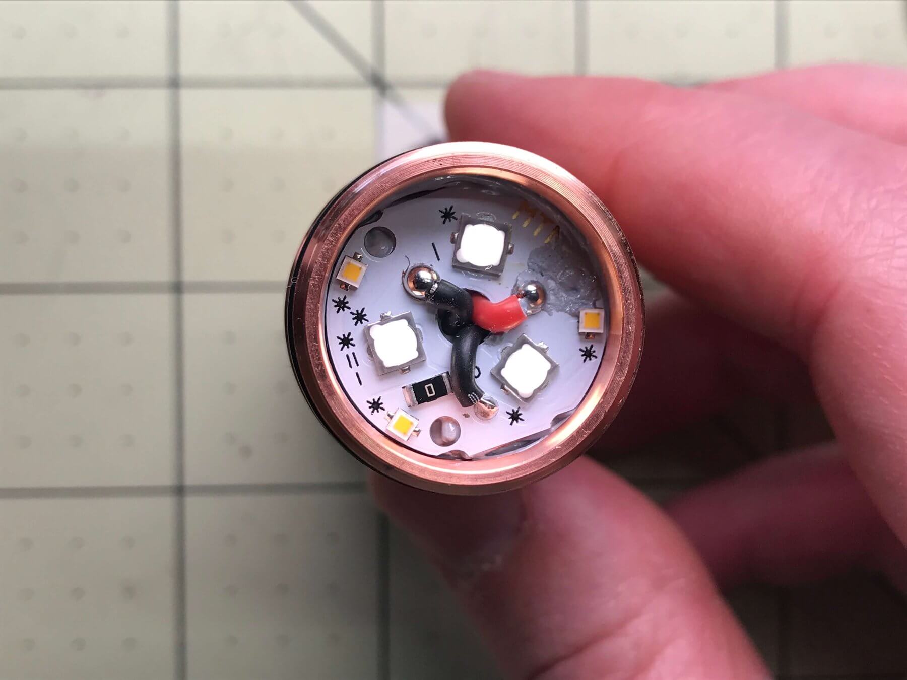
I did red first (because it was in the center), then secondary ground (so I could get that marking tape out of the way), and primary ground last.
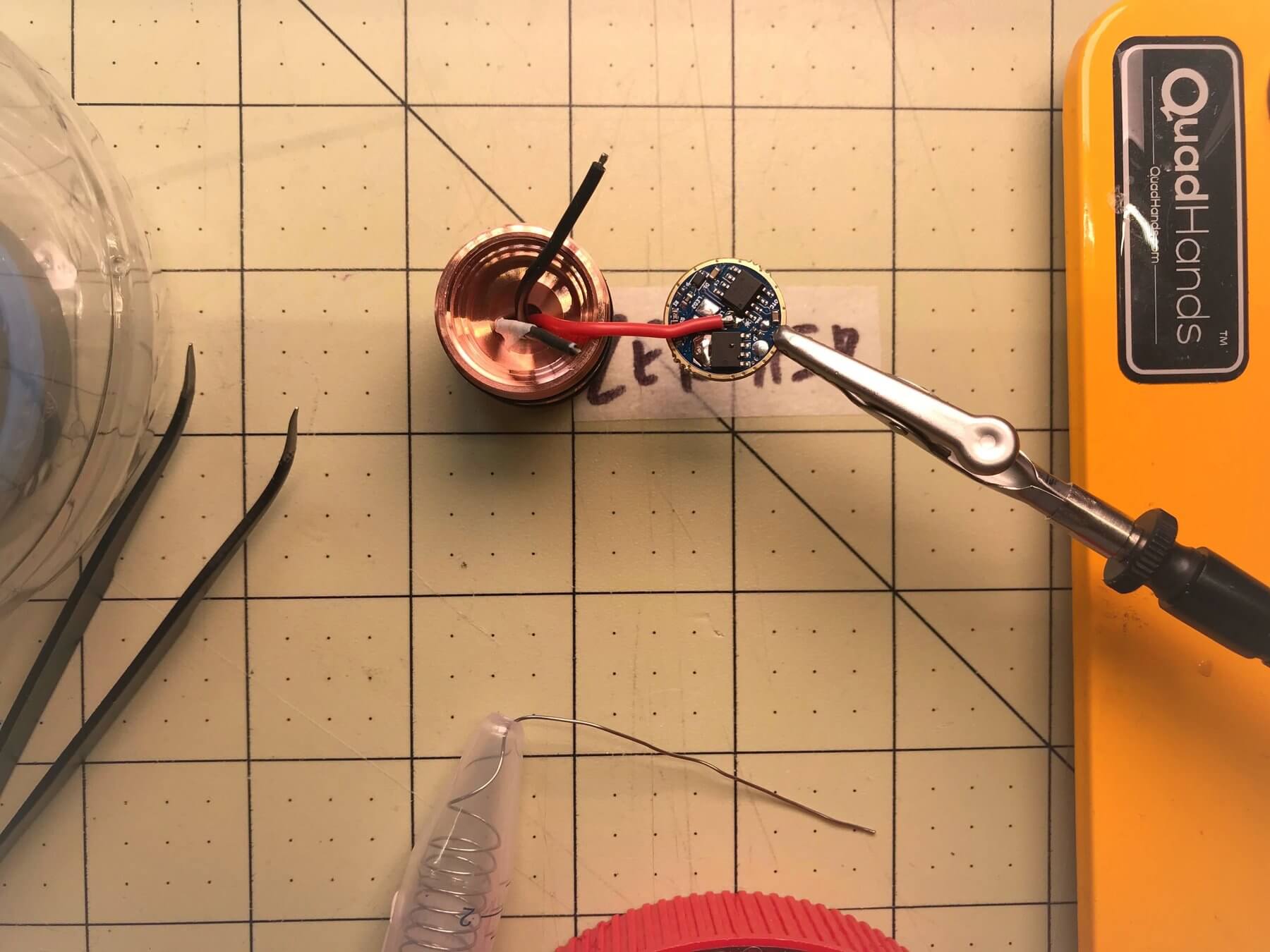
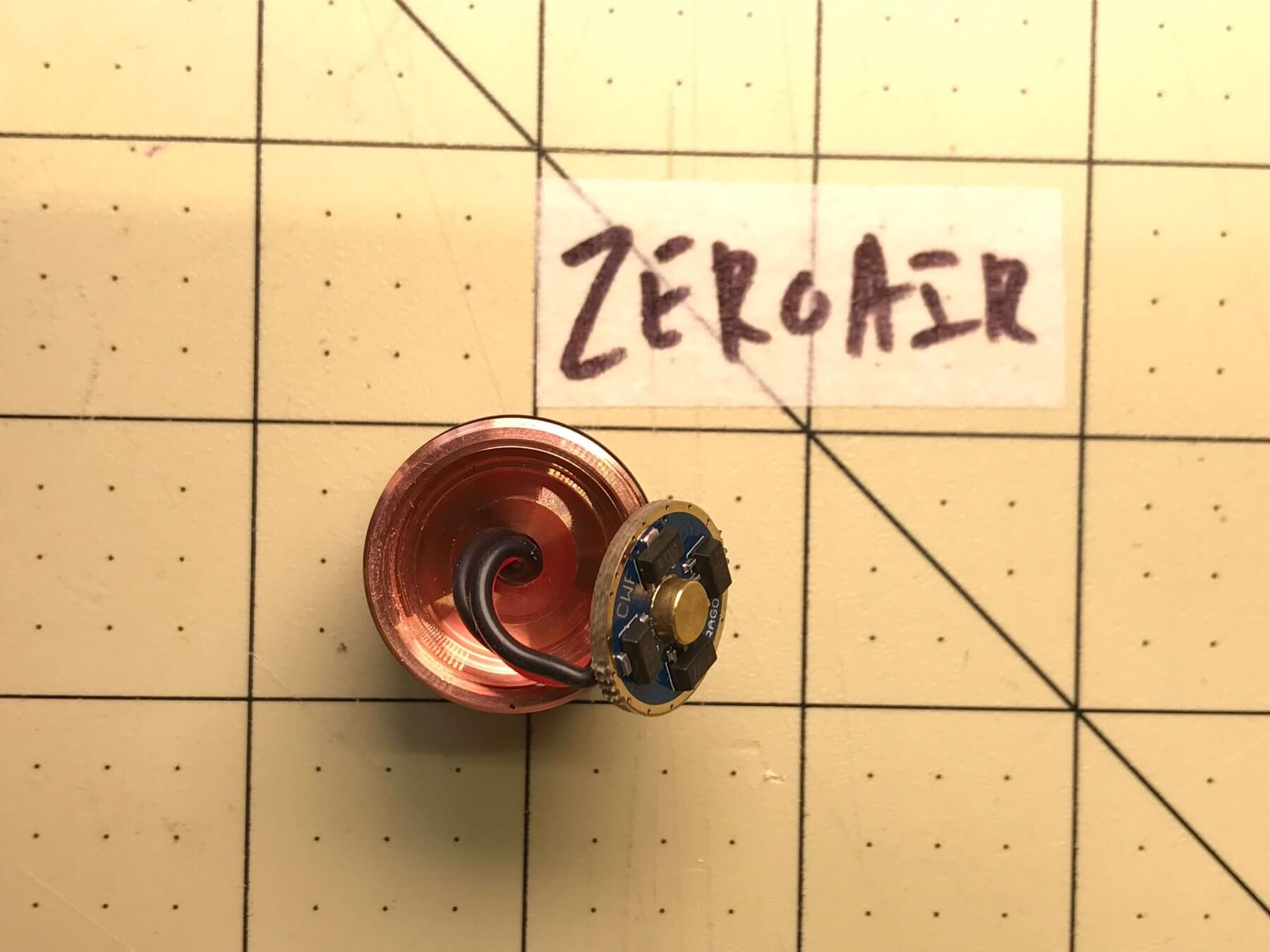
Here’s the finished shot. This isn’t an ideal placement, but I didn’t feel like moving it. Ideally, the leads would come off the driver so that there wasn’t any stress once the driver was squished into place. So there’s definitely a better orientation – you’ll have to figure out what’s best for your build.
Flip the driver and stuff it into the pill. I haven’t said it yet but hope it’s clear if you’ve made it this far (or even opened the post, really). That brass button is the positive connection for the cell, so that should be your way to understand the orientation of the driver.
Helpful Tools, pt. 2
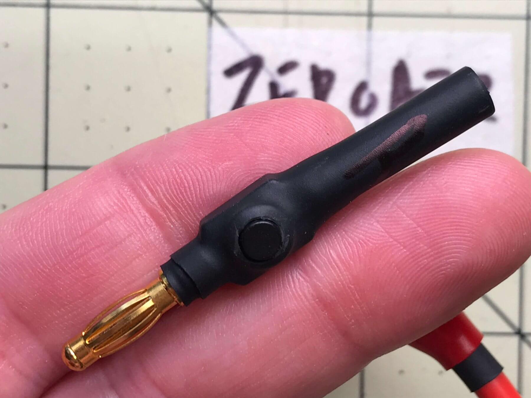
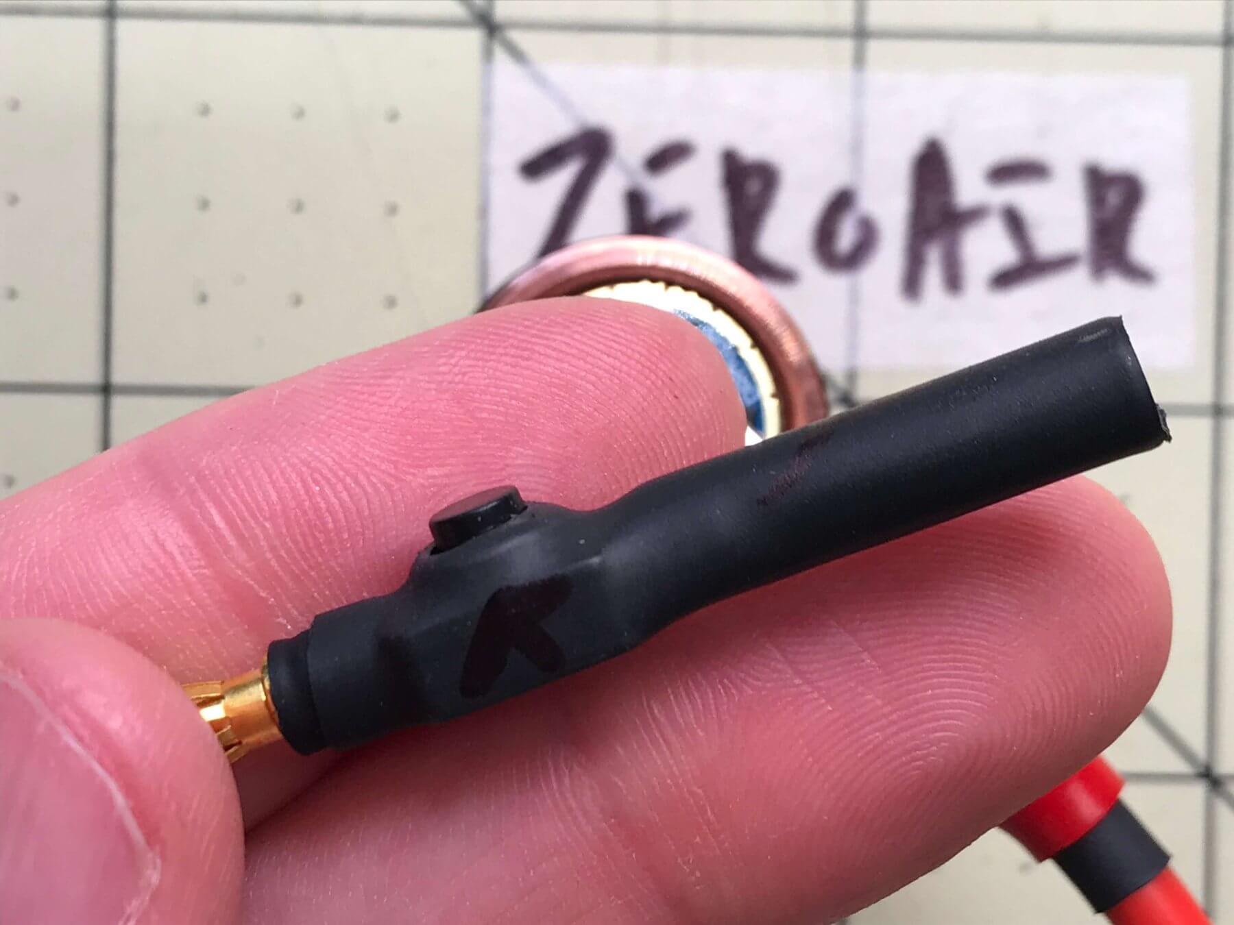
After building my bench power, I realized I needed more flashlight-specific tools. Often I tested flashlights with mechanical clickies, but when connected to bench power I lost the ability to (easily) change modes. So I ordered a few reverse and a few forward clickes, and built them into banana plugs like this. Now, whenever I am testing a light with a reverse clicky, I just throw this clicky in line with my ground wire from the bench power, and I have easy access to all the modes!!!
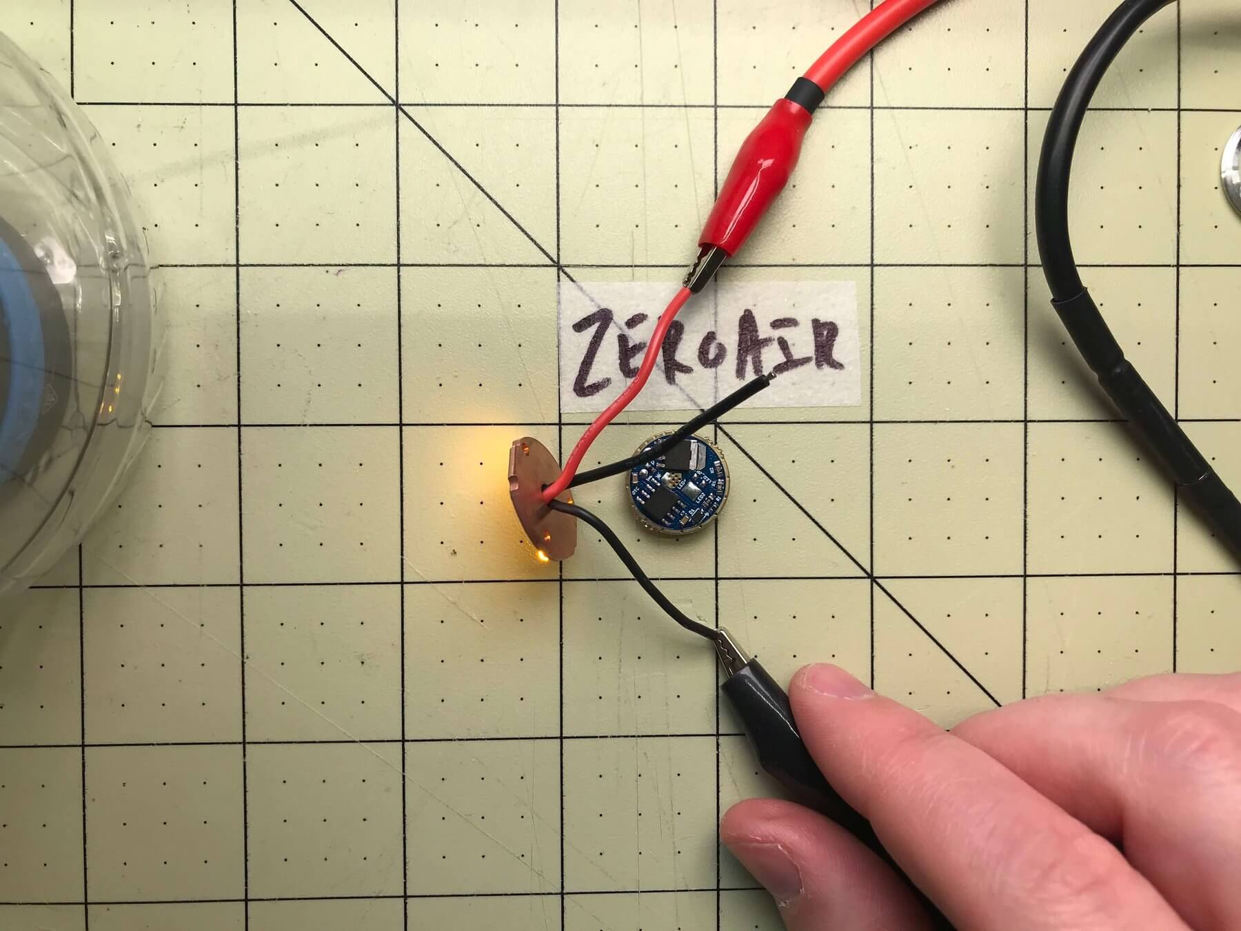
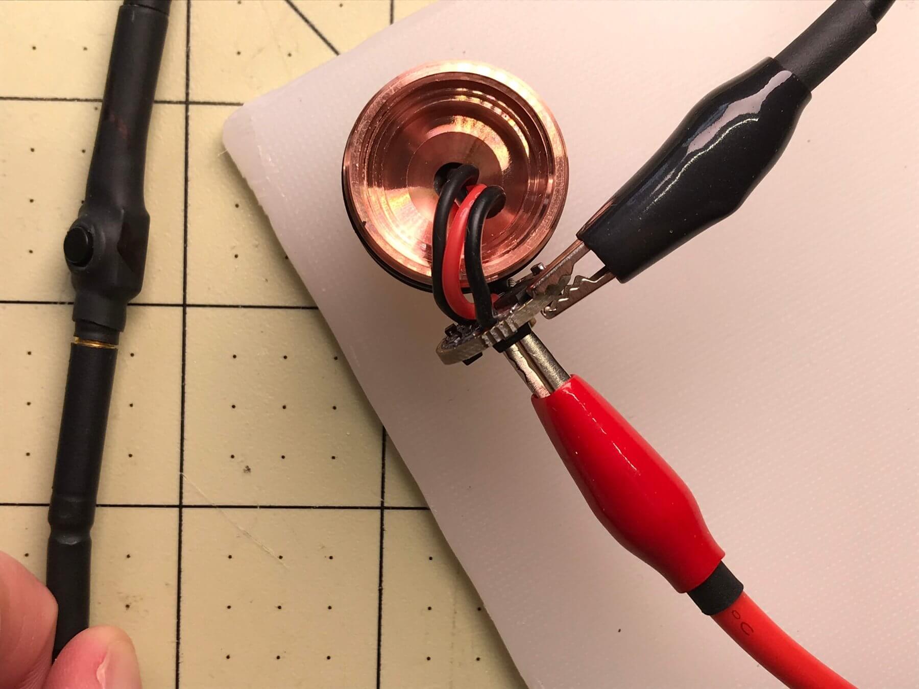
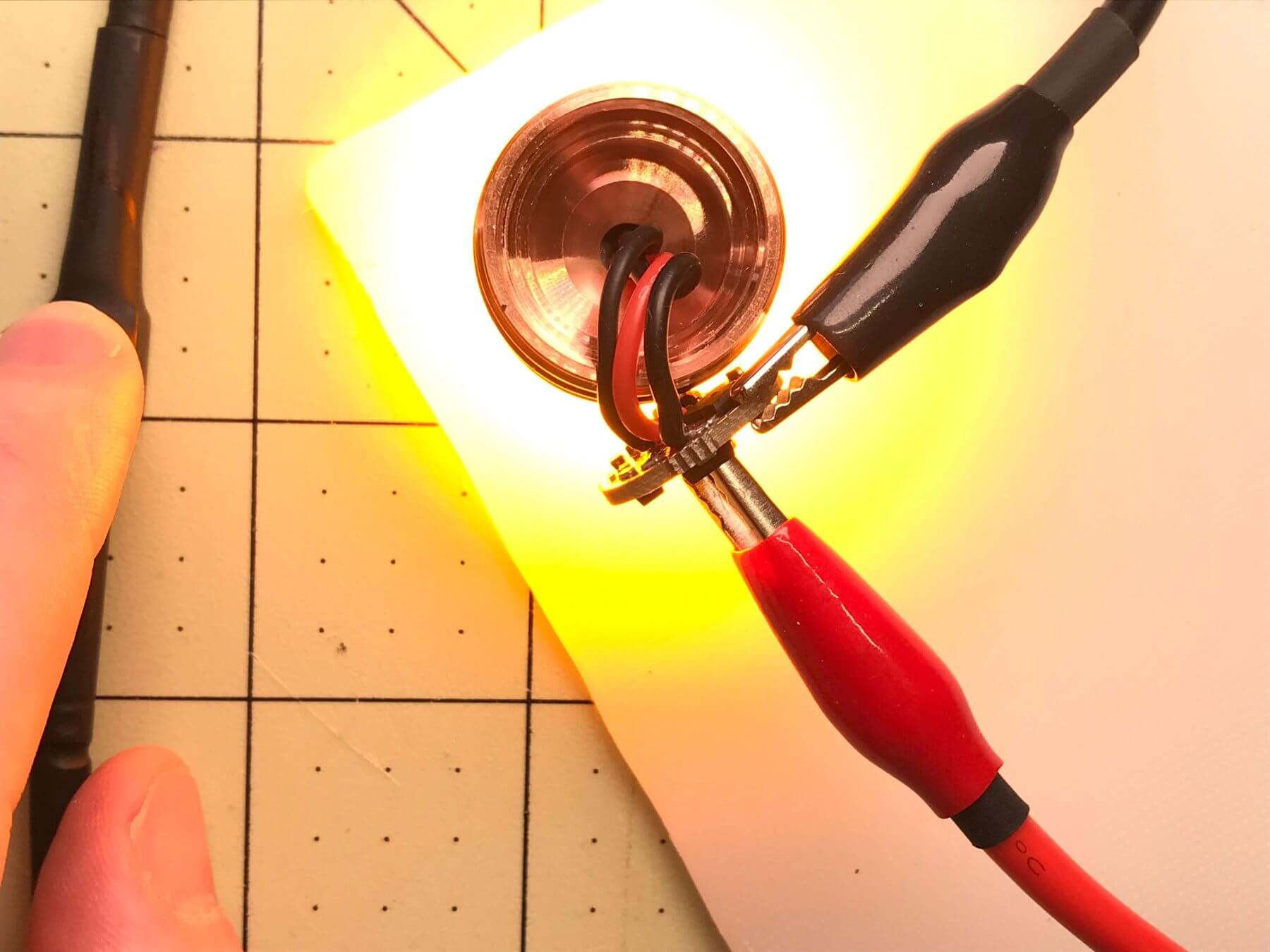
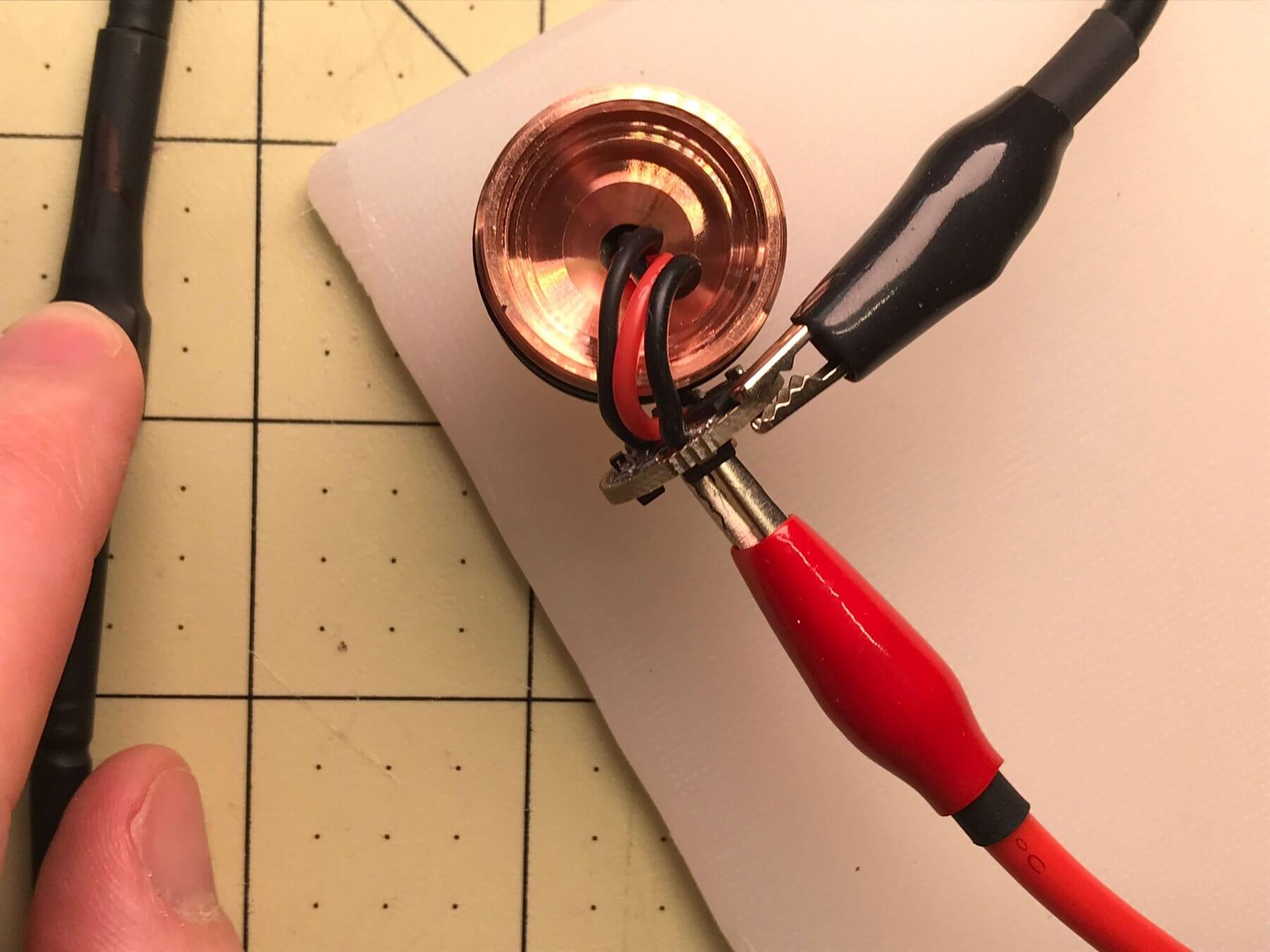
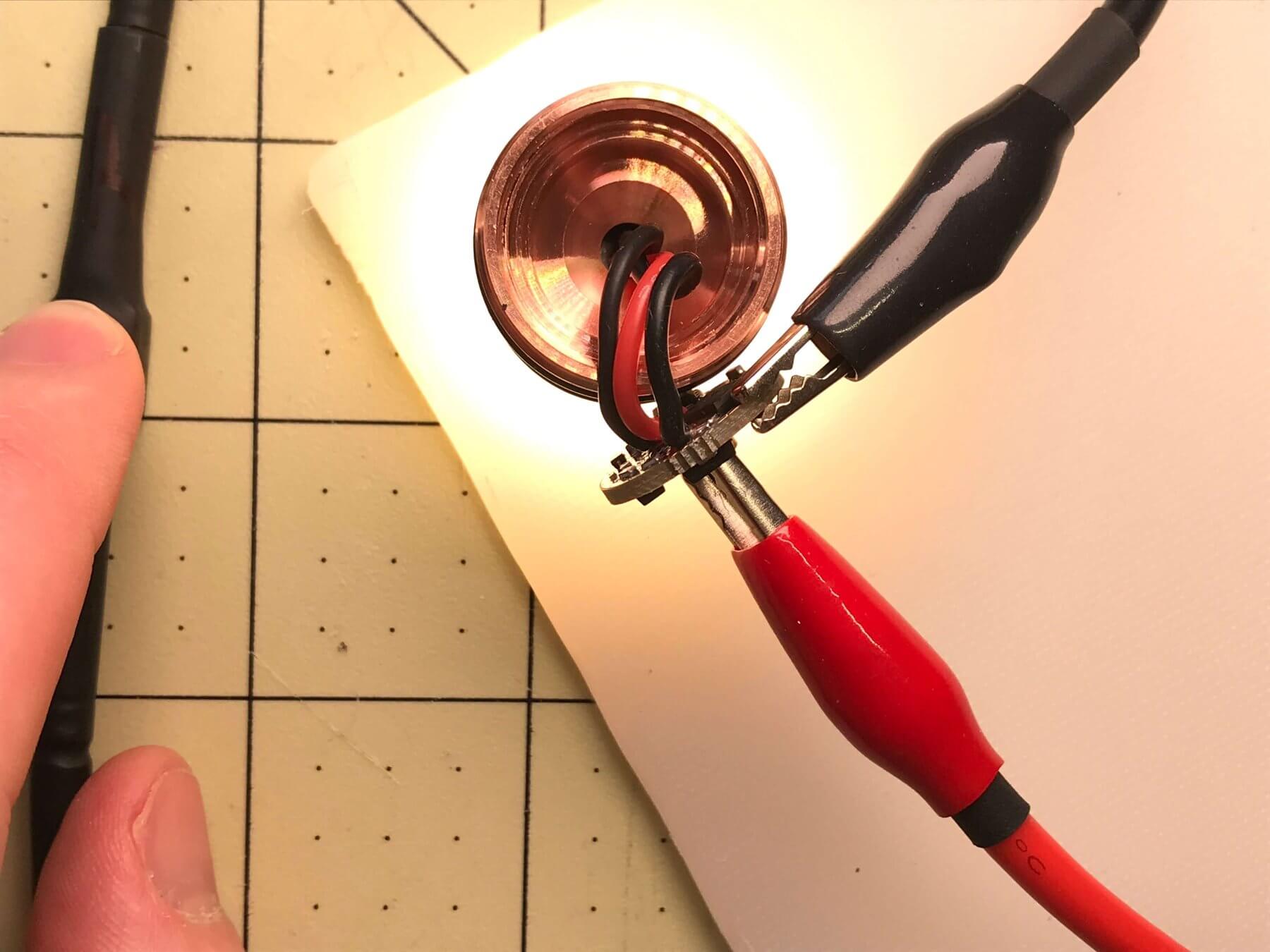
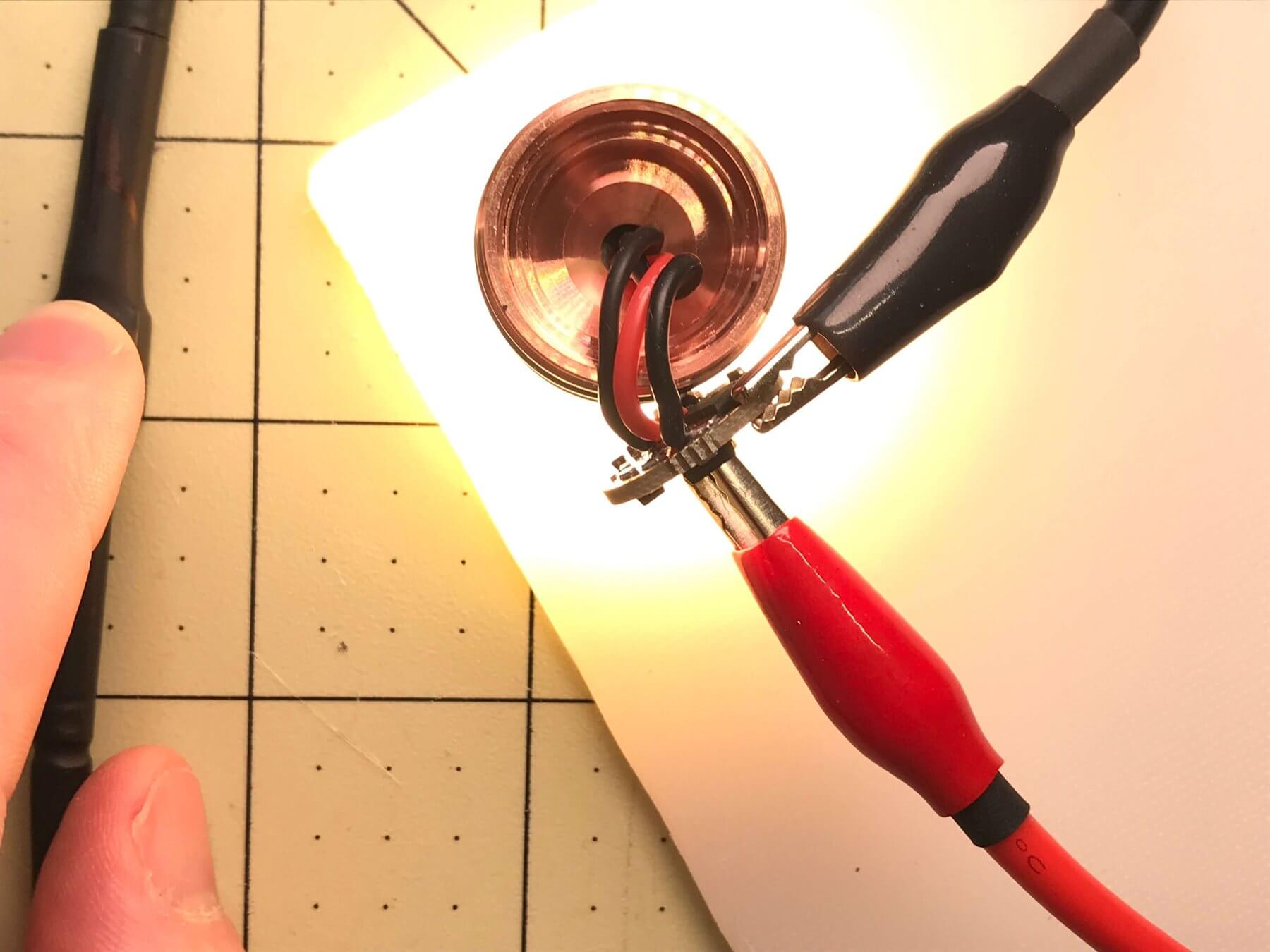
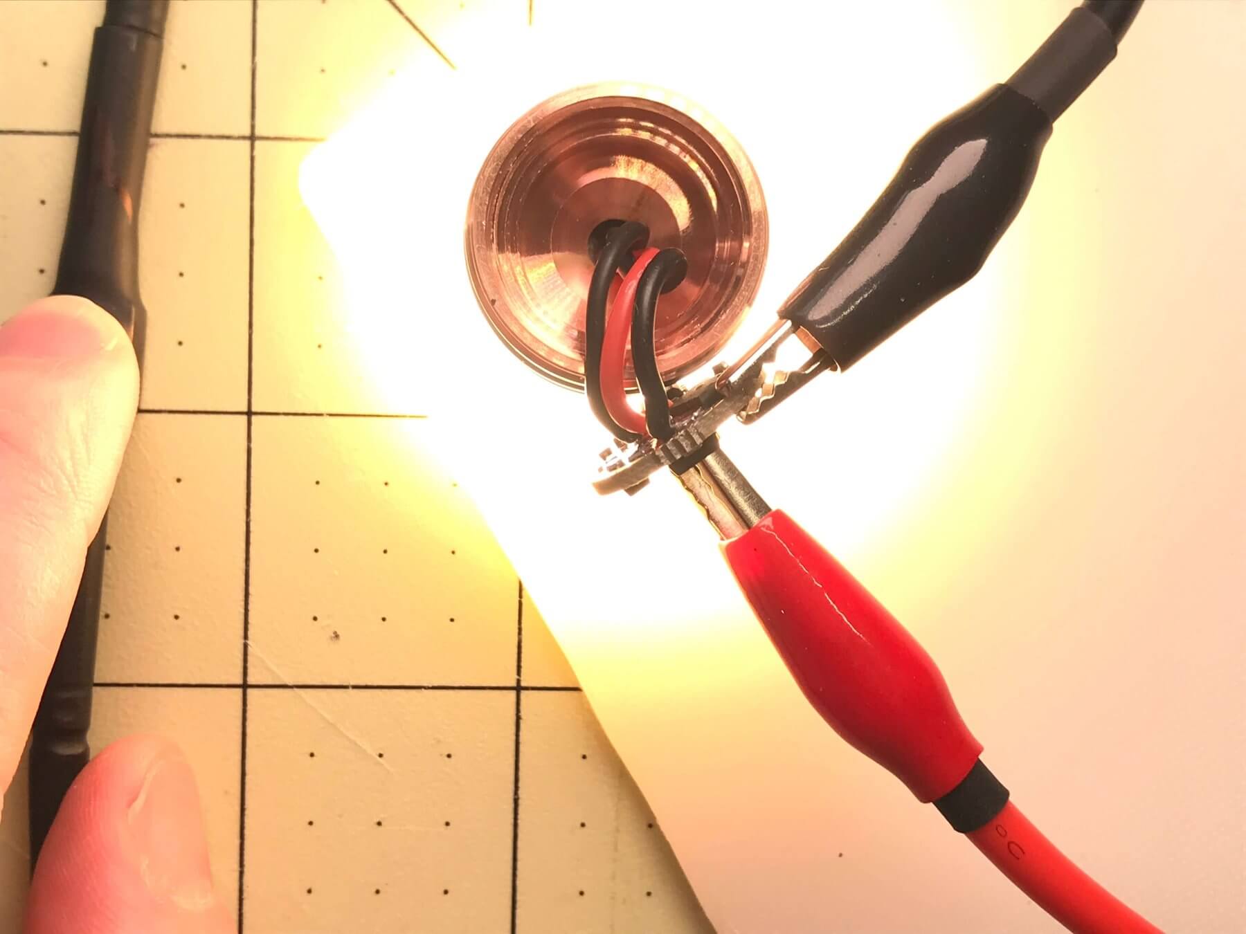
Before I button everything up I want to test it again. Red goes to the brass button on the driver. Ground goes through my reverse clicky switch, and then to the edge of the driver. Alligator clips are massively helpful in this endeavor.
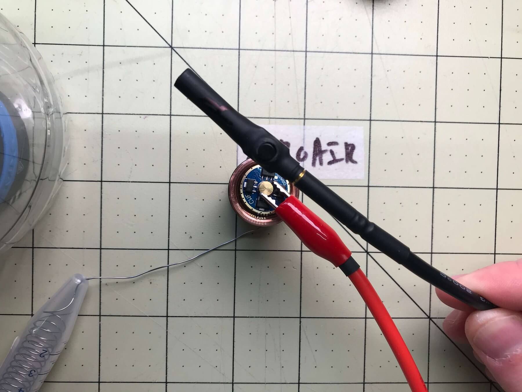
Click on that reverse clicky!!!
Testing Testing One Two Three
Amber XQ-E modes both seem to work fine!
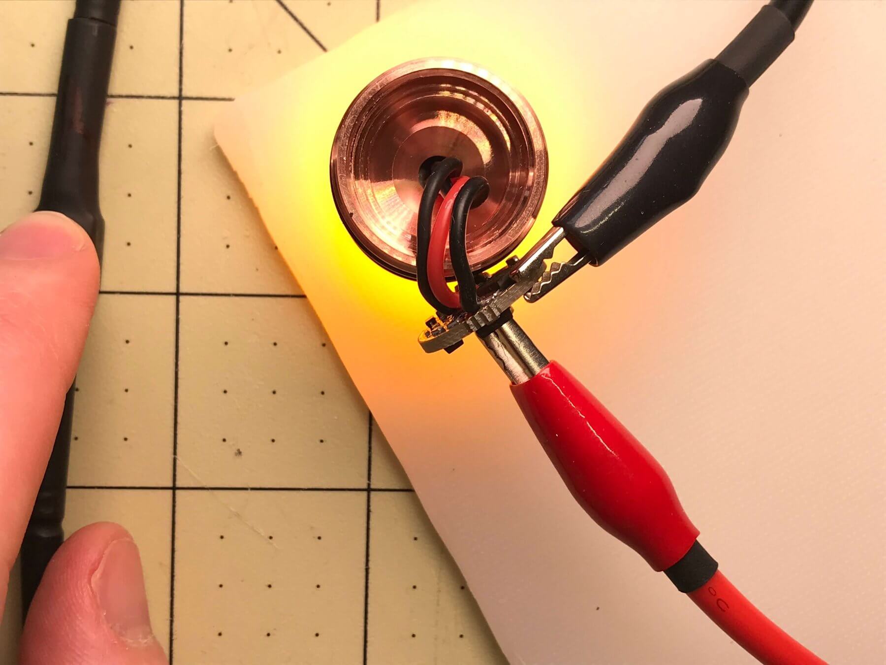
Nichia 219c modes also work fine! I only see 5 main outputs here, but I think there were 6. I think the default group is
1- low red,high red,ml,5,15,35,50,100
even though that’s not stated on the CWF page. Anyway, the light works, time to button it up!
How do I undo the damage I have done?
I went wrong in two ways on this build. I could go back and clean them up, but I chose not to. But you can learn from my mistakes!
First, I used much too much thermal paste. “If some is good, more is better” is definitely not the right phrase here. Use very little!!
Secondly the leads off the driver. I should have been much more careful about their placement so that they didn’t interfere with the pill when pressed in. As you can see below, the bend is a bit unnaturally. This could be a wear point down the road.
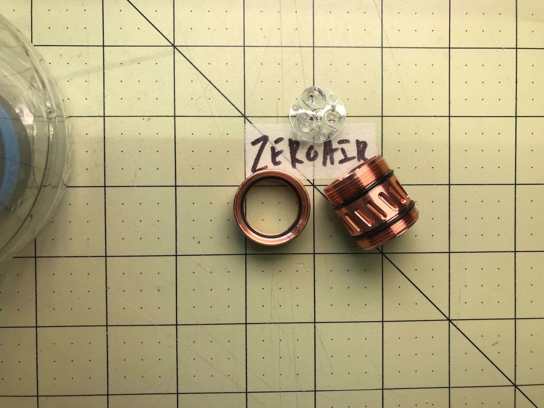
TGIHRR (Thank Goodness it Has a Retaining Ring)
Ok on to finishing finally! Fortunately this host uses a screw-in retaining ring. Push the driver in, and screw down the aluminum retaining ring. If it didn’t have this retaining ring, I’d need to bridge the edge of the driver board (ie the cell ground connection) to the pill. Many lights require this!
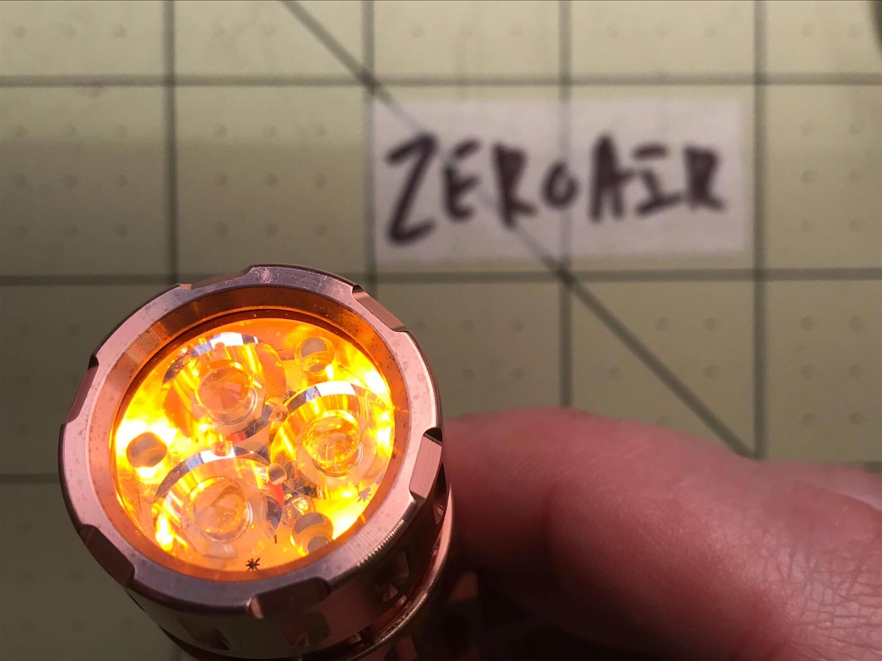
Pre-Flight Check
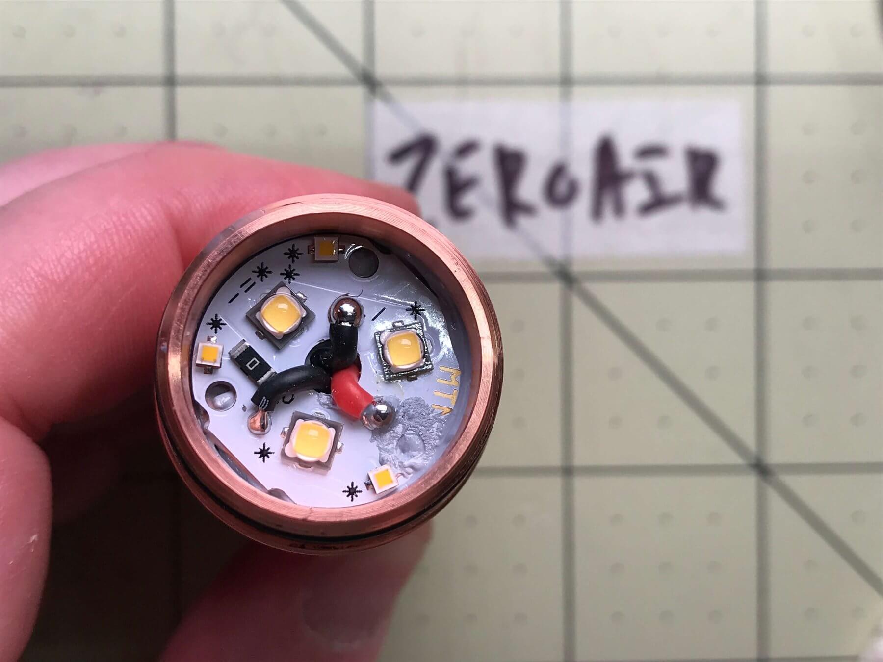
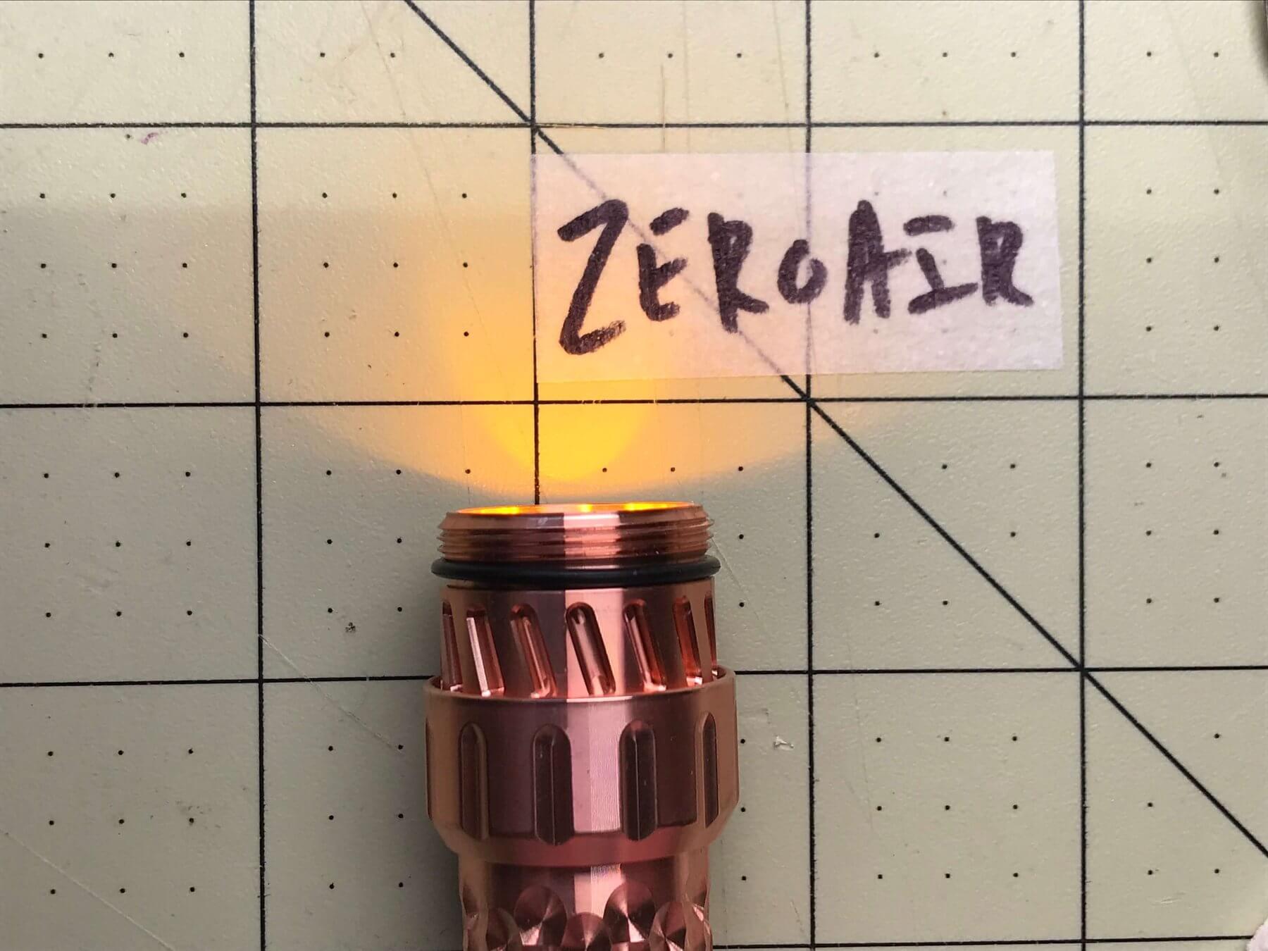
With the Dragon Flashlight driver installed into the pill and the emitters placed in long ago, it’s time for a test! No need to screw on the bezel yet.
It Verks! Amber, both modes.
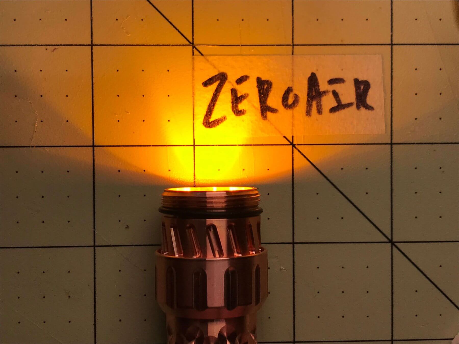
And low, of the mains.
Throw that optic in there. Be sure the legs get in those holes (holes which in my case, have a bunch of thermal paste oozing through, whoops).

Screw down that bezel!
And pose for that money shot of your first completed build!
Conclusion
What I like
- Ease of build
- Retaining ring on the driver side
- Chamfered holes to prevent abrasion on wires
What I don’t like
- Cost
- Host is coated
I hope this info on how to install a Dragon flashlight driver is helpful or at least interesting! It was a fun build for me, and I’ve enjoyed using a light I actually built! You could do this build for much less than this one cost, and as a beginner that’s probably a better choice. A q-lite driver and a convoy S2+ is a very usual starting point and can be done for probably well under $50.
Discover more from ZeroAir Reviews
Subscribe to get the latest posts sent to your email.
A good write up on this process. I recently did this upgrade twice for my FidgetHQ Aonic flashlights. I had the same question about which lead was for the primaries and which was for the secondaries. I just guessed that the smaller was for the secondaries and luckily I was right. The hardest point may have been getting the driver tucked back in the head without stressing the solder points. So your point about thinking of the orientation of the wiring before soldering is one I would emphasis.
Thanks for the comment Mike! I randomly revisited my Aonic review yesterday and I wished I had that one back. That’s a nice light! Maybe if I could find one in titanium…. hmmm…
Any idea how the stress because of poor orientation of these wires reduces current flow to the emitters? IE could output be lowered by poor orientation of the wires here?
I’m not an electronics expert but I would think the connection would have to be pretty poor the reduce the output enough that you would notice. Especially because we’re dealing with such low voltages.
Pingback: CWF Dragon Driver (in MechForce MechTorch) Review - ZeroAir Reviews
Pingback: Goodbye 2019, Welcome 2020! - ZeroAir Reviews